

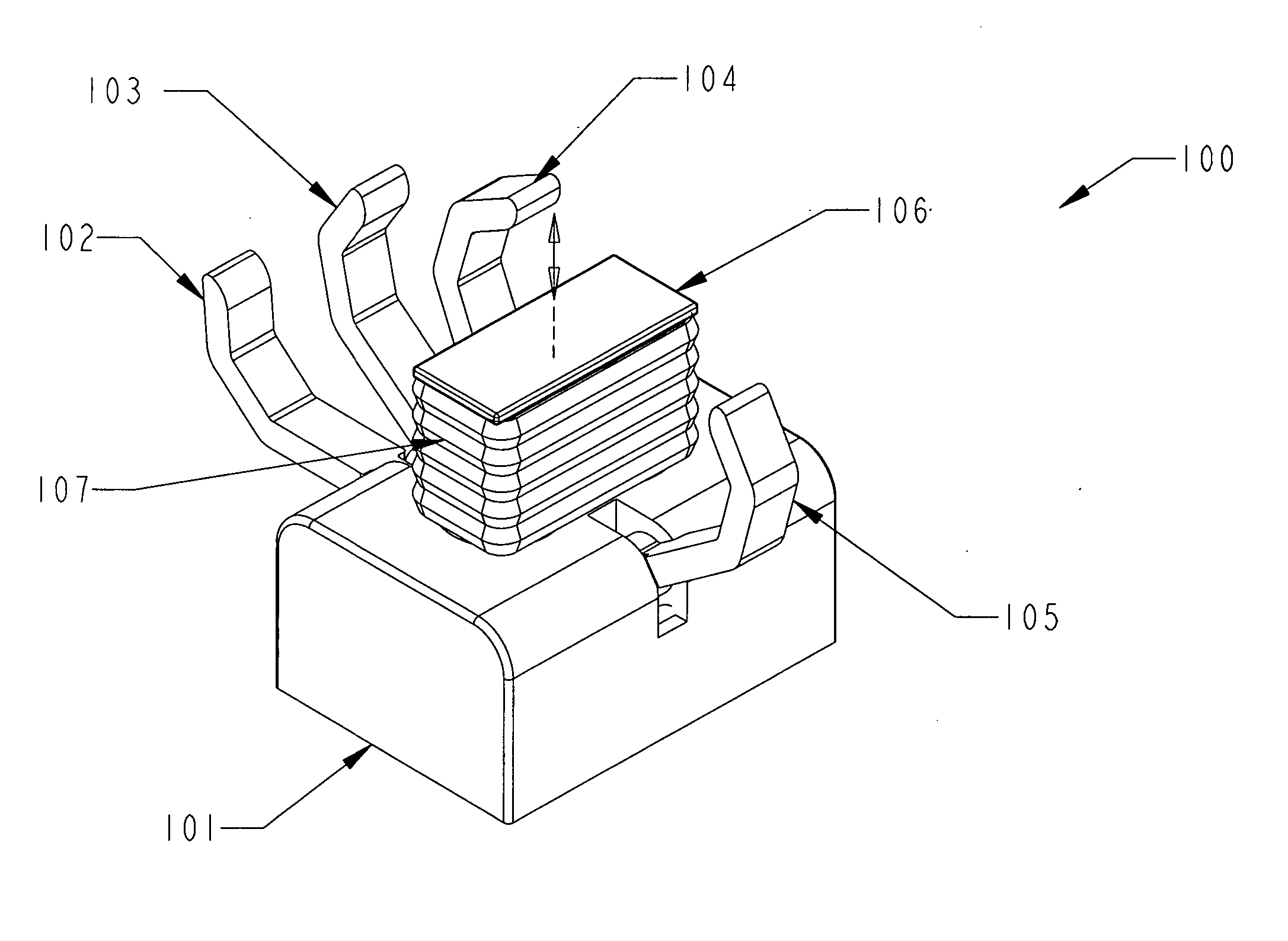
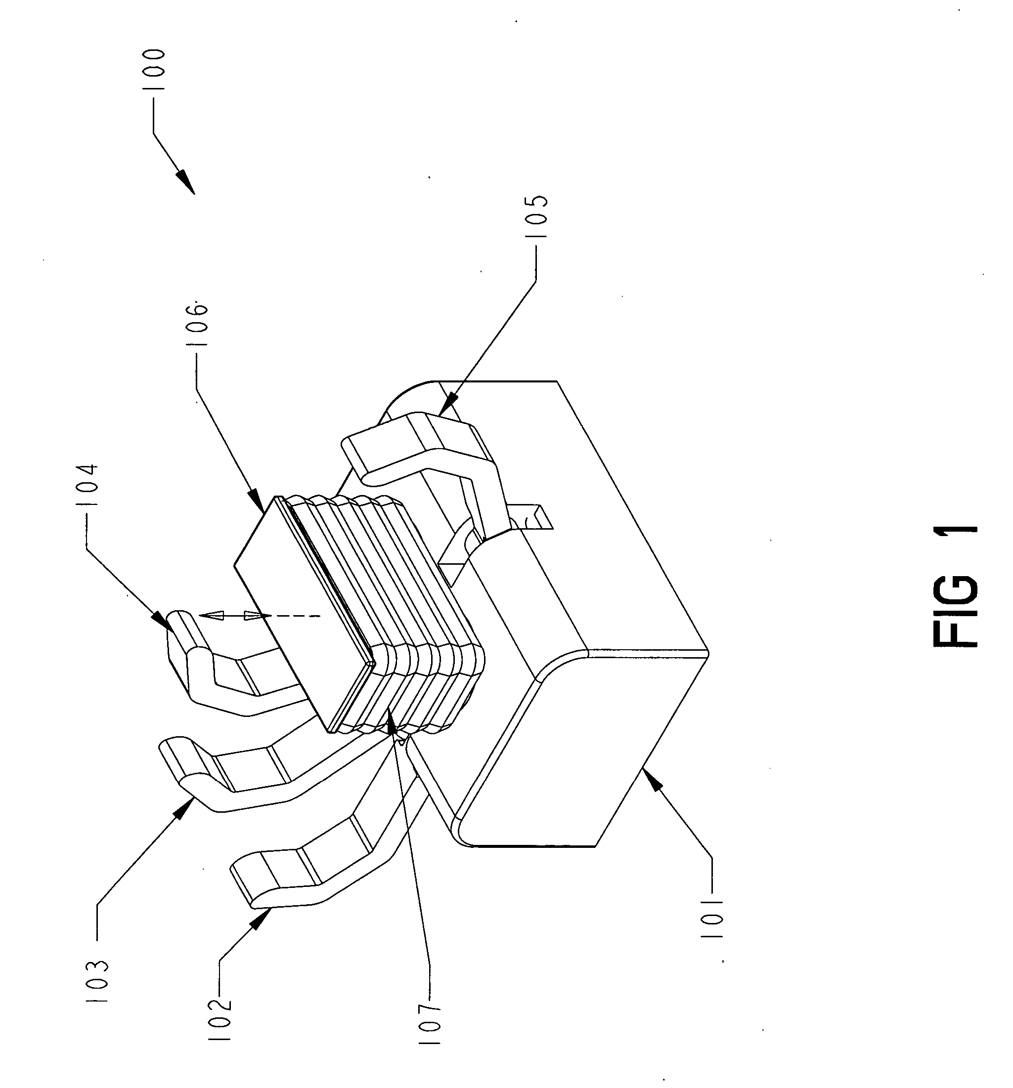
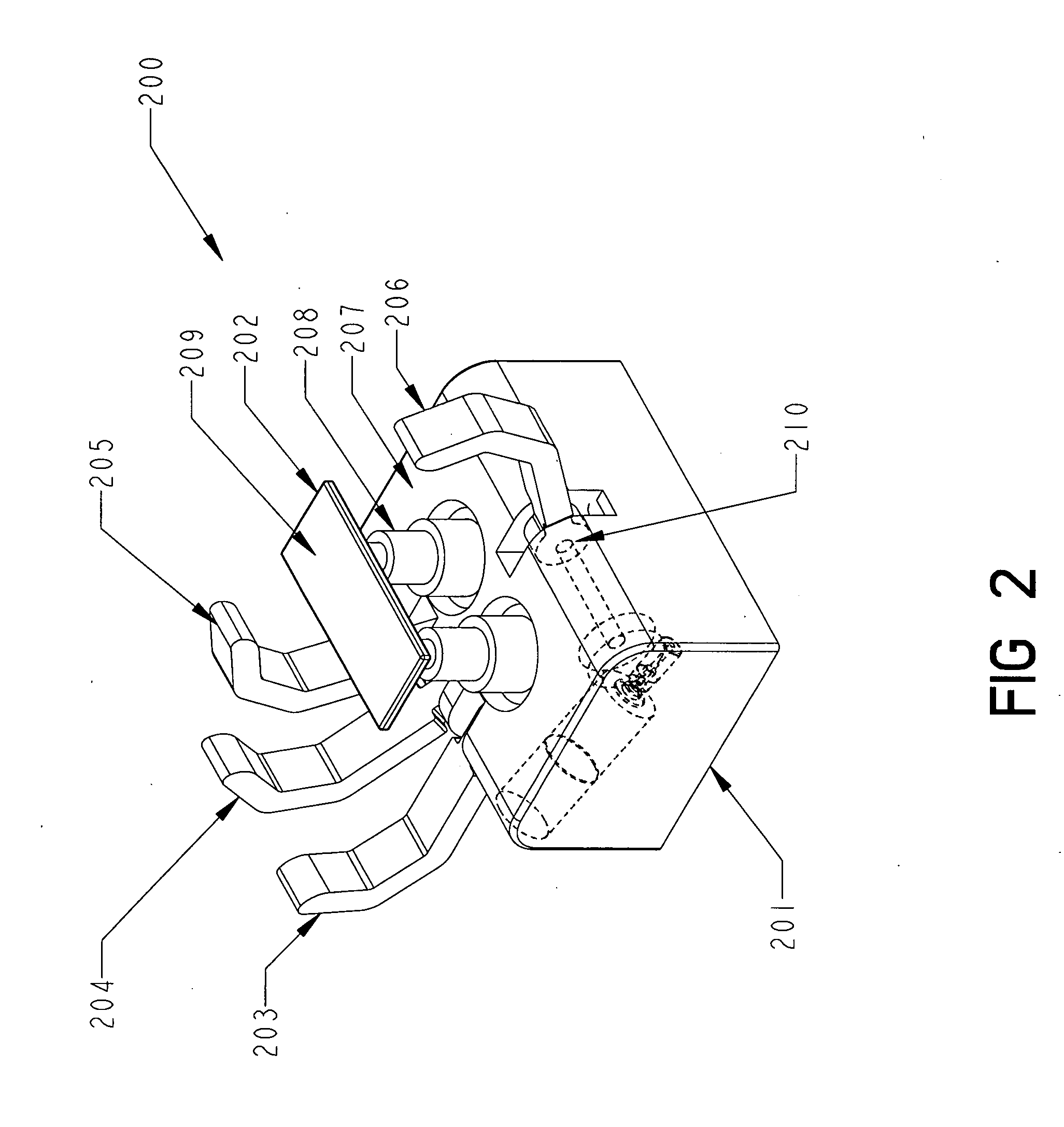
Robotic hand with extendable palm
a technology of hand and palm, applied in the field of robots, can solve the problems of limited palm participation in a wide range of desirable grasps, difficult manufacturing, and high maintenance costs, and achieve the effect of reducing the difficulty of hand mechanical complexity, and reducing the difficulty of hand participation
- Summary
- Abstract
- Description
- Claims
- Application Information
AI Technical Summary
Benefits of technology
Problems solved by technology
Method used
Image

Examples
Embodiment Construction
Preferred Embodiments
[0035] The present invention can best be described by first considering the types of grasps that are performed by the human hand. Broadly speaking, grasps can be divided into two groups, precision grasps and power grasps. A precision grasp is executed between the terminal digit pads of the thumb and fingers. The precision grasp is used when the hand is required to perform delicate handling or manipulation. A power grasp is executed between the surfaces of the fingers / thumb and the palm and is used when a secure grasp is essential.
[0036] In many circumstances, the function of the hand is to securely grasp an object; movement or manipulation of the object, once grasped, is performed by an arm. In such circumstances a power grasp is preferred. In other circumstances, when the object is large, only a power grasp provides sufficient force to secure the object against the force of gravity or other externally applied forces. For example, consider grasping a handle of...
PUM
 Abstract
Description
Claims
Application Information