
Tiled display device

a technology of display device and display screen, which is applied in the field of display device, can solve the problems of lcd device having a limit in implementing a large screen, one of the electronic display devices, and increasing the demand for a liquid crystal display devi

Active Publication Date: 2006-01-19
LG DISPLAY CO LTD
View PDF13 Cites 83 Cited by
  • Summary
  • Abstract
  • Description
  • Claims
  • Application Information

AI Technical Summary

Benefits of technology

[0014] An object of the present invention is to prevent or decrease visible distinction between a seam area (artificial boundary) and the rest of the area by providing each display device with an appropriate compensation device for preventing seam phenomena occurring due to a structural anomaly of a tiled display device. Namely, variations in brightness and chromaticity occurring at the seam area are corrected or alleviated for several pixels, thereby preventing or decreasing visual observation of a seam line. Such compensation is individually performed on each of display panels.
[0016] To achieve these and other advantages and in accordance with the purpose of the present invention, as embodied and broadly described herein, a tiled display device includes: a plurality of display panels each having an image display part in which a plurality of pixels are formed; a support frame having a plurality of panel receiving portions such that the plurality of display panels are tiled side by side and received therein; a plurality of light guides each formed of an optical fiber bundle and disposed on the corresponding display panel, each light guide having an image receiving surface and a display surface that have different surface areas from each other, wherein a light and an image transmitted from the image display part are received by the image receiving surface and are reproduced on the display surface; and a black matrix film provided on the display panel and having apertures and a light shielding portion to prevent the light from being leaked to a dead zone between optical fibers in the optical fiber bundle.

Problems solved by technology

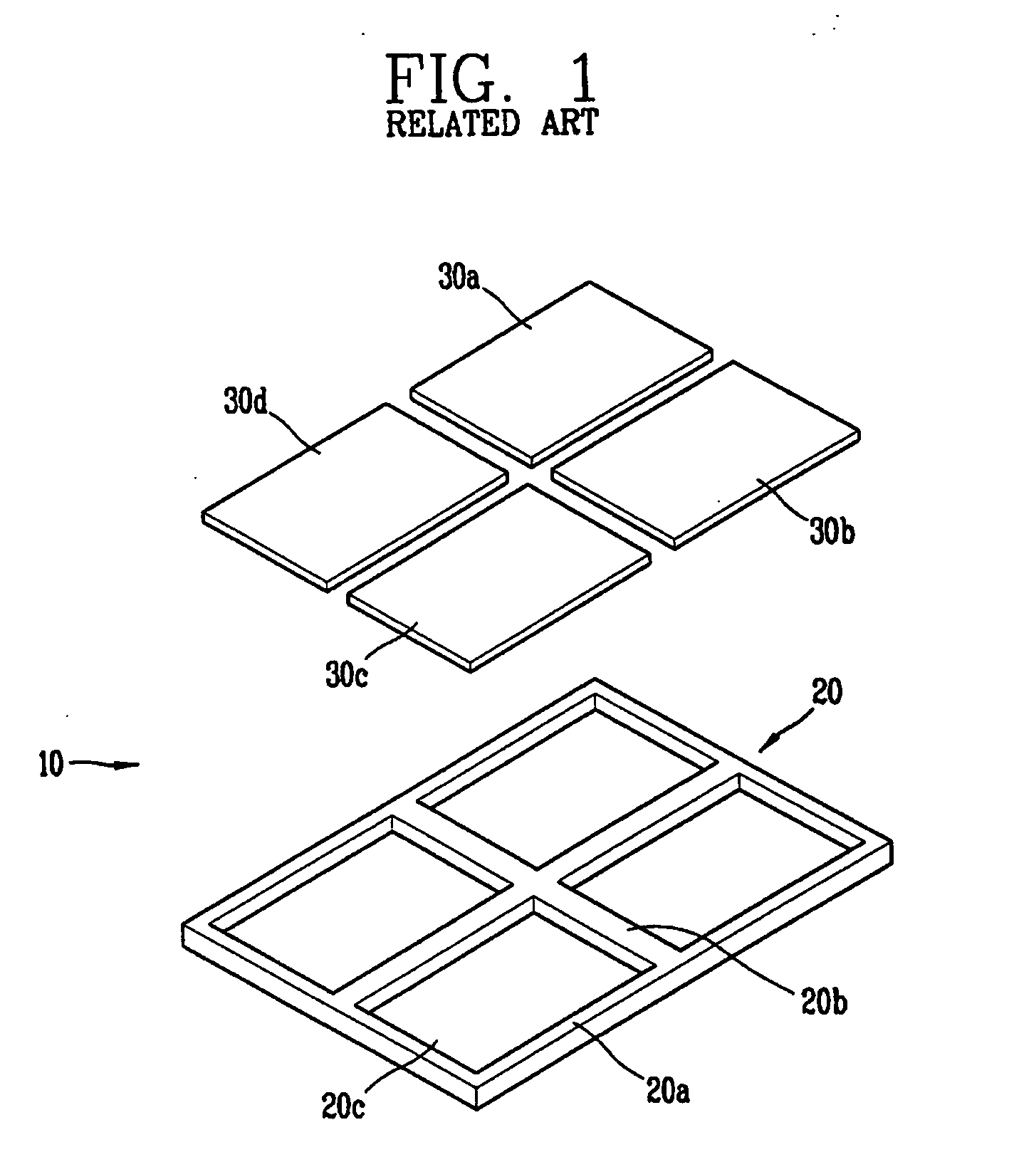
The demand for a liquid crystal display (LCD) device, one of the electronic display devices, which is desirably thin and light and consumes small power, is rapidly increasing.
However, the LCD device has a limit in implementing a large screen by enlarging a size of a liquid crystal panel itself because of its own characteristics.

Method used


Image

  • Tiled display device
  • Tiled display device
  • Tiled display device

Examples


Embodiment Construction

[0029] Reference will now be made in detail to the preferred embodiments of the present invention, examples of which are illustrated in the accompanying drawings.

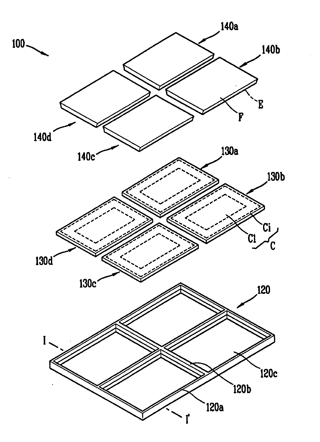
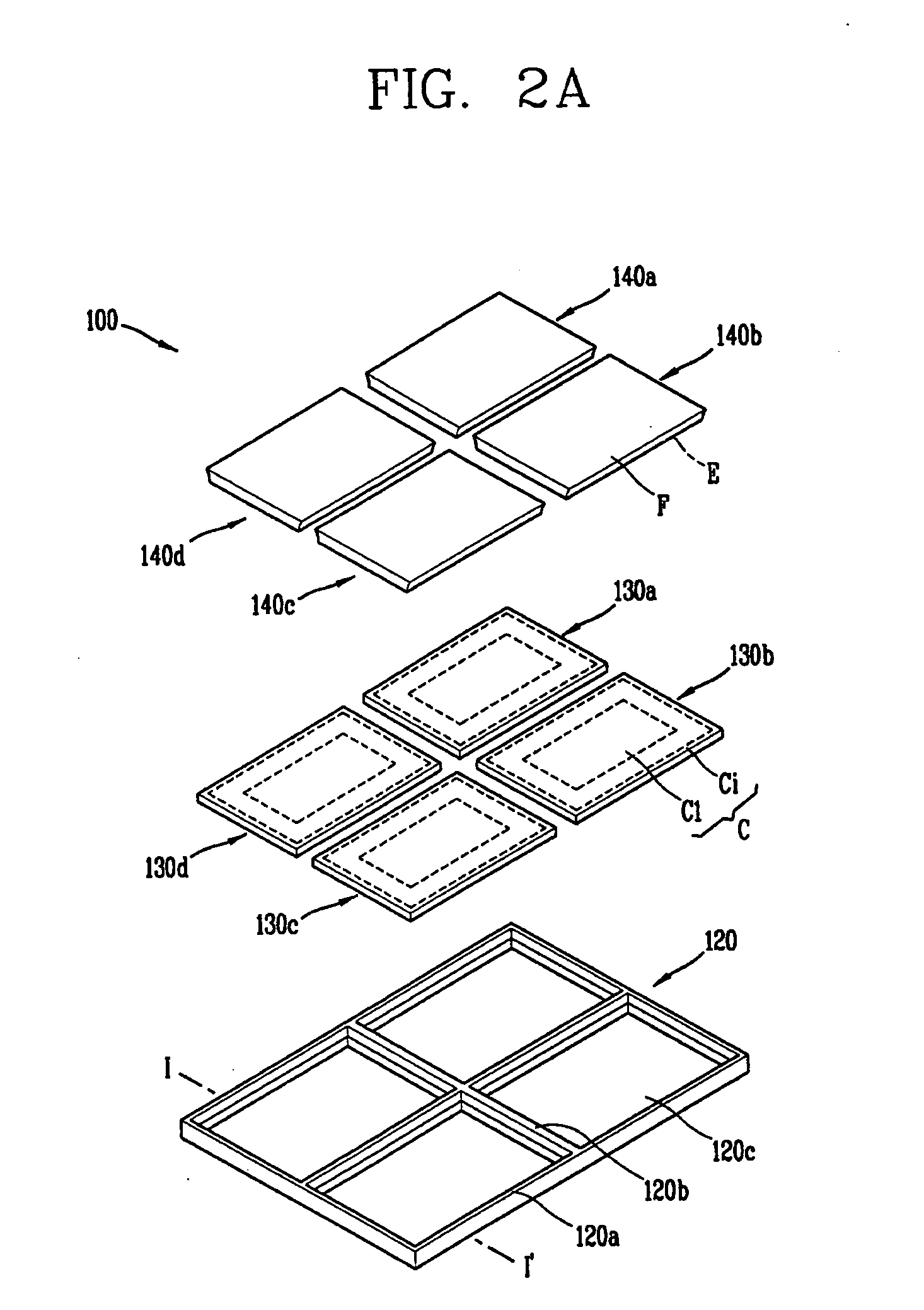
[0030]FIG. 2A is a schematic exploded perspective view which illustrates a tiled display device in accordance with a first exemplary embodiment of the present invention. As shown, the tiled display device 100 in accordance with the present invention is formed such that a plurality of display panels 130a-130d individually having light guides 140a-140d thereon are tiled and fixed side by side by a support frame 120.

[0031] The support frame 120 includes an outer wall frame 120a forming an outer wall, a partition wall frame 120b interposed between display panels, and a bottom plate 120c which the light guides 140a-140d and the display panels 130a-130d are placed on. Each of the display panels 130a-130d is received within a space formed by the partition wall 120b and the outer wall frame 120a.

[0032] A plurality of pixels are ...


PUM

PropertyMeasurementUnit
surface areasaaaaaaaaaa
surface areaaaaaaaaaaa
sizeaaaaaaaaaa

Abstract

A tiled display device is disclosed. The disclosed tiled display device includes a plurality of display panels each having an image display part in which a plurality of pixels are formed. The tiled display device includes a support frame having a plurality of panel receiving portions such that the plurality of display panels are tiled side by side and received therein. The tiled display device also includes a plurality of light guides each formed of an optical fiber bundle and disposed on the corresponding display panel, each light guide having an image receiving surface and a display surface that have different surface areas from each other, wherein a light and an image transmitted from the image display part are received by the image receiving surface and are reproduced on the display surface. In addition, the tiled display device includes a black matrix film provided on the display panel and having apertures and a light shielding portion to prevent the light from being leaked to a dead zone between optical fibers in the optical fiber bundle.

Description

[0001] This application claims the benefit of the Korean Application No. 50854 / 2004, filed Jun. 30, 2004, which is hereby incorporated by reference. BACKGROUND OF THE INVENTION [0002] 1. Field of the Invention The present invention relates to a display device, and more particularly, to a tiled display. [0003] 2. Background of the Related Art [0004] As visual information transmitting devices become increasingly important, the scope of an electronic display device industry is being enlarged. The demand for a liquid crystal display (LCD) device, one of the electronic display devices, which is desirably thin and light and consumes small power, is rapidly increasing. Also, with the improved standard of living of consumers, a product having a larger size and better image quality is in more demand. [0005] However, the LCD device has a limit in implementing a large screen by enlarging a size of a liquid crystal panel itself because of its own characteristics. Thus, what is called a projecti...

Claims


Application Information

Patent Timeline
Patent Type & Authority Applications(United States)
IPC IPC(8): G02F1/133
CPCG02F1/13336G02F1/133524G02F1/133514G02F1/133512G02F1/1343
Inventor JIN, HYUN SUKKIM, MIN JOO
Owner LG DISPLAY CO LTD
Learn More