Image data processing circuit and image processing apparatus including the same

a data processing circuit and image processing apparatus technology, applied in the field of image data processing circuits and image processing apparatus, can solve the problems of high printing speed, large data quantity, and circuits that cannot offer compression and decompression processes, and achieve the effect of optimizing circuit structur

Inactive Publication Date: 2006-02-02
SHARP KK
View PDF14 Cites 7 Cited by
  • Summary
  • Abstract
  • Description
  • Claims
  • Application Information

AI Technical Summary

Benefits of technology

[0011] The image data processing circuit according to the present invention includes the transfer controlling section for selecting any one of the parallel input / output mode in which the input transfer and the output transfer are performed in parallel, the parallel input mode in which input image data are compressed in parallel, and the parallel output mode in which data decompressed in parallel are transferred to the output section. This allows selecting a suitable structure in accordance with required compression / decompression processing speed and a required image data transferring speed, and thus the image data processing circuit of the present invention can be adapted to both high-speed machines and low-speed machines with a structure suitable for the respective machines. In other words, the image data processing circuit in the parallel input mode and the image data processing circuit in the parallel output mode are used in a pair for high-speed machines, while the image data processing circuit in the inputting / outputting parallel transfer mode can be used by itself for medium-speed machines. Thus, the structure of the circuit can be optimized depending on the application thereof. This eliminates the necessity of designing different circuits for high-speed machines and for medium-speed machines. Consequently, the number of developing processes and the cost can be saved, whereby low-price products can be provided in short developing terms.

Problems solved by technology

However, so-called high-speed digital multifunction peripherals (hereinafter, referred to as high-speed machines) have high scanning speeds and high printing speeds and, in some cases, a single compression circuit and a single decompression circuit can not offer compression and decompression processes which follow the inputting and outputting rates.
Image data transferred through the aforementioned portions is not compressed and thus has a large data quantity, which tends to restrict the processing capacity.
This tends to restrict the processing capacity more significantly when the number of bits per pixel is increased, when the resolution is increased or when the inputting and outputting rates are increased for increasing the image quality.
However, the compression and decompression circuits have large circuit scales and, if the compression and decompression circuits are configured to be arranged in parallel for high-speed machines, the ASIC will have surplus performance and involves a high cost, while if the ASIC is optimized for medium-speed machines, the ASIC will not satisfy the performance requirement of high-speed machines.

Method used


Image

  • Image data processing circuit and image processing apparatus including the same
  • Image data processing circuit and image processing apparatus including the same
  • Image data processing circuit and image processing apparatus including the same

Examples


first embodiment

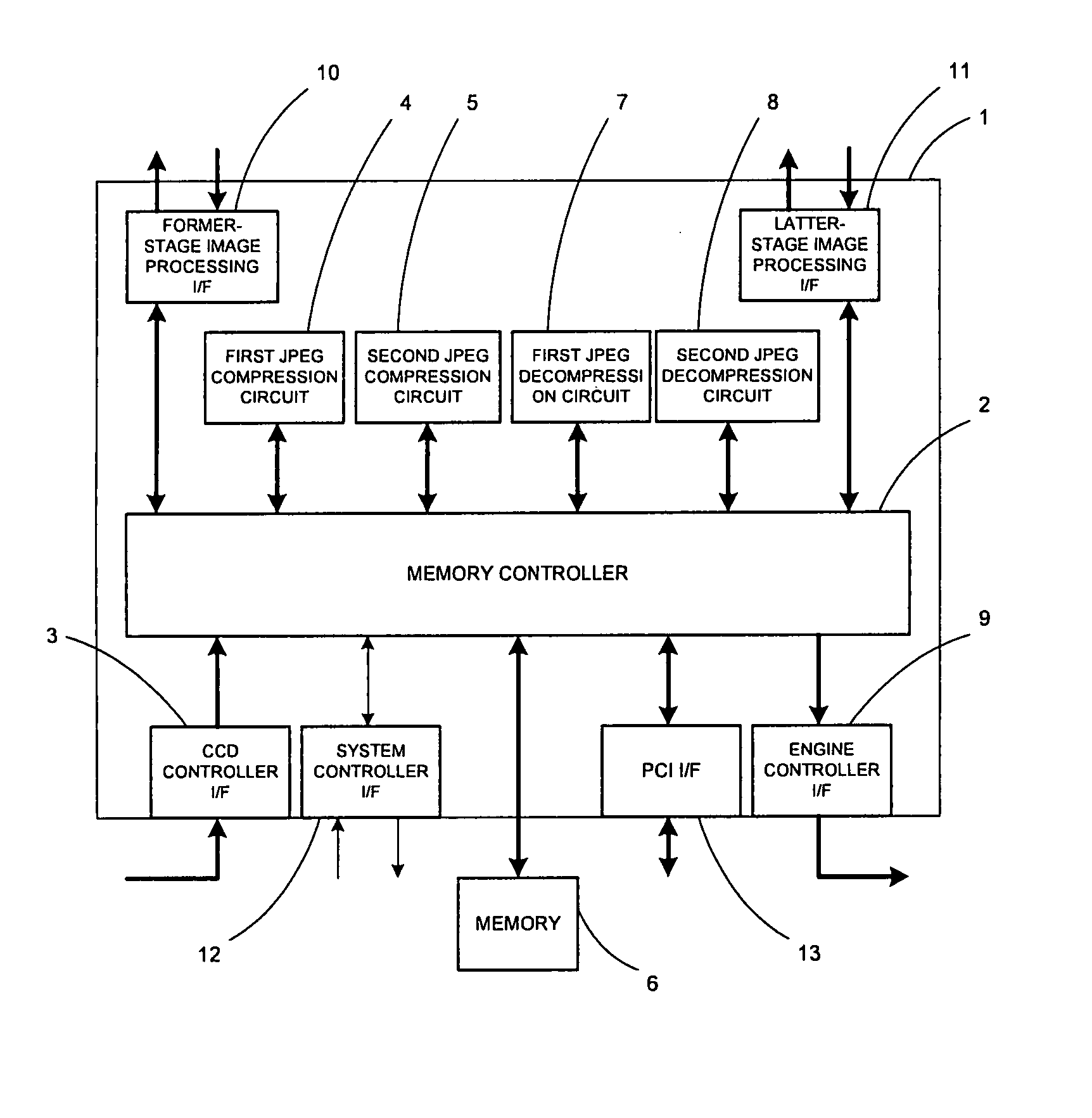
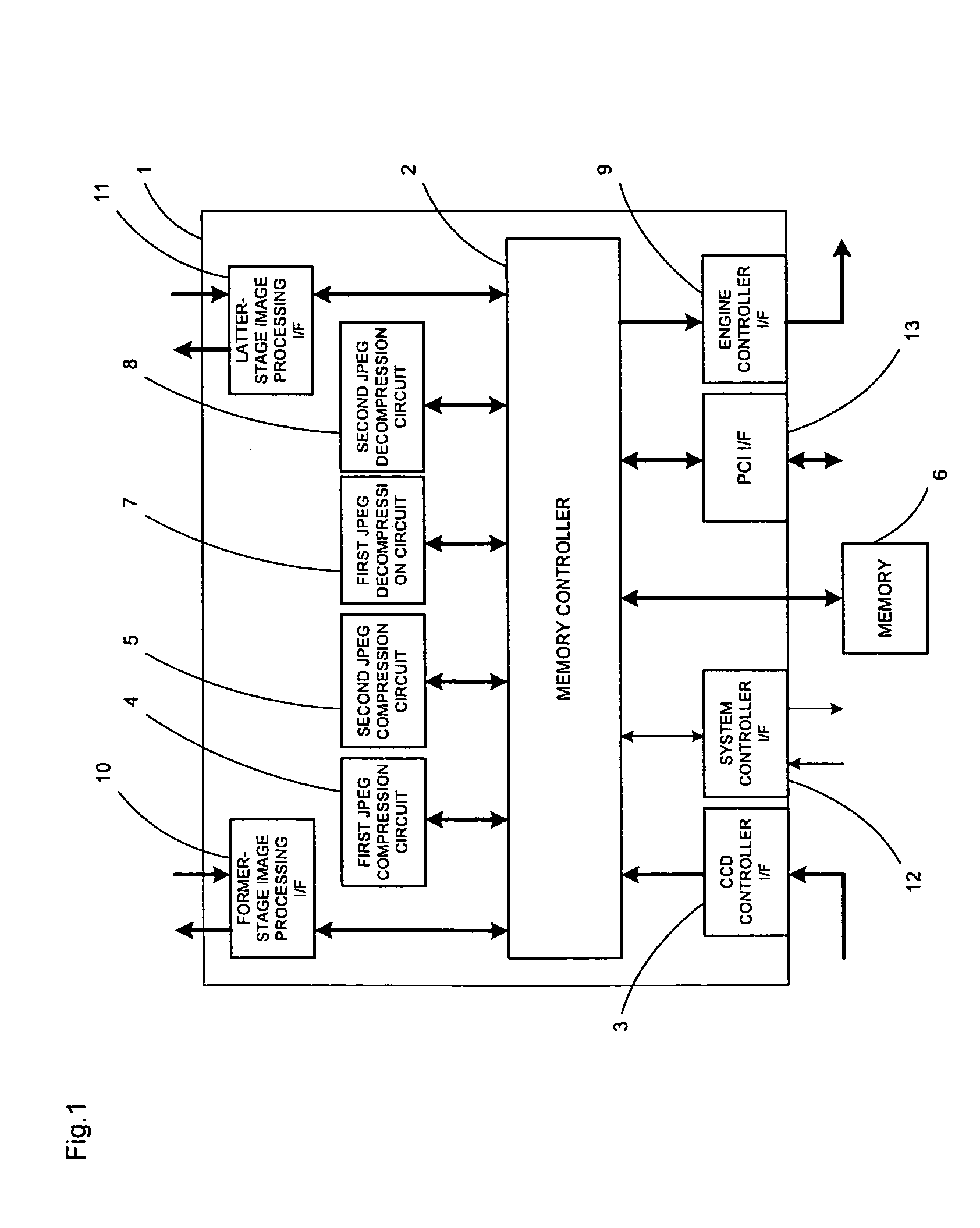
[0034] In the present embodiment, there will be described exemplary structures of the image data processing circuit and the image processing apparatus according to the present invention. FIG. 1 is a block diagram illustrating an exemplary structure of the image data processing circuit according to the present invention. As illustrated in FIG. 1, the image data processing circuit 1 includes a CCD controller I / F 3 for inputting image data from a scanner section, a first JPEG compression circuit 4 and a second JPEG compression circuit 5 as compressing sections for compressing image data, a first JPEG decompression circuit 7 and a second JPEG compression circuit 8 as decompressing sections for decompressing image data, an engine controller I / F 9 for outputting image data to a printing section, a PCI I / F 13 for receiving and sending image data from and to external devices such as an HDD through a PCI bus, a former stage image processing I / F 10 and a latter stage image processing I / F 11 f...

second embodiment

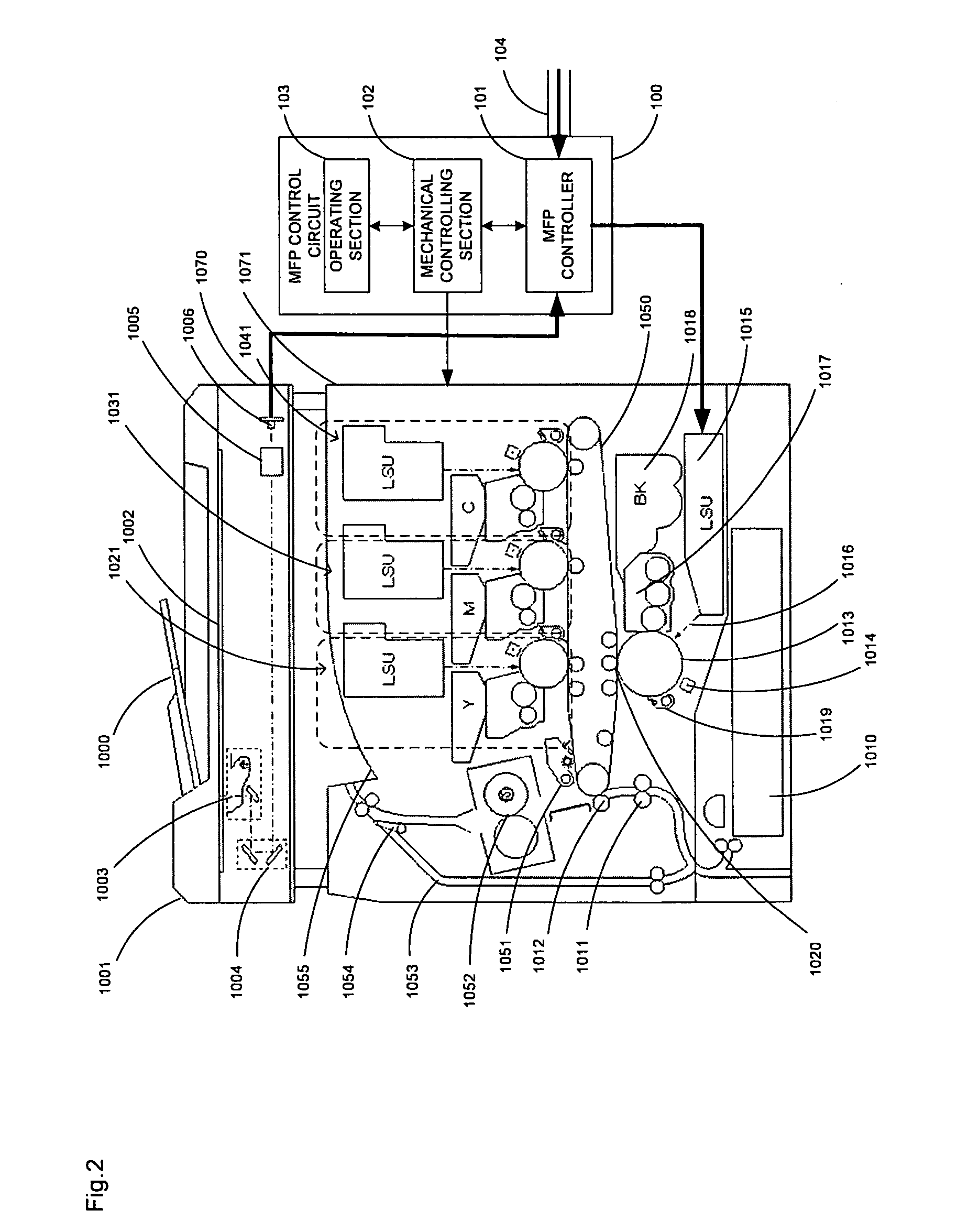
[0042] In the present embodiment, there will be described image data processes which are executed by the image data controller 1 in the image processing apparatus of FIG. 3. In the structure of FIG. 3, the CCD controller I / F 3 of the image data controller 1 is connected to the CCD controller 110 and image data from the scanner section 1070 is input thereto. Further, the engine controller I / F 9 is connected to the engine controller 112 and outputs image data to the printing section 1071. Further, the memory 6 is connected to the memory controller 2. The image processing controller 111 is connected to the former stage image processing I / F 10 and the latter stage image processing I / F 11. Further, the HDD 16 is connected to the PCI I / F 13 through a PCI bus.

[0043]FIG. 5 is an explanation view illustrating transferring processes executed by the memory controller 2 for controlling image data transfers among the first and second JPEG compression circuits 4 and 5, the first and second JPEG ...

third embodiment

[0050] In the present embodiment, there will be described a case where a single compression circuit and a single decompression circuit as described in the second embodiment can not perform processes followable to the inputting and outputting data transferring rates, namely a structure for high-speed machines.

[0051] As previously described, for high-speed machines, the structure of the image data controller needs to be modified in order to increase the input / output data transferring capacities and the compression / decompression processing speed for providing a required processing capacity. The image data controller according to the present invention includes two compression circuits capable of performing parallel processes and two decompression circuits capable of performing parallel processes, in order to increase the compression / decompression processing speeds. For applications thereof to high-speed machines, these circuits may be connected in parallel to increase the compression p...


PUM


Abstract

An image data processing circuit including: an input section for inputting image data; a plurality of compressing sections which are capable of compressing the input image data solely or in parallel; a plurality of decompressing sections which are capable of decompressing the compressed image data solely or in parallel; an output section for outputting the decompressed image data; a transferring section for transferring image data between a memory and of the input section, the compressing sections, the decompressing sections and the output section individually; and a transfer controlling section for selecting a mode from a parallel input/output mode, a parallel input mode and a parallel output mode.

Description

CROSS-REFERENCE TO RELATED APPLICATION [0001] This application is related to Japanese Patent Application No. 2004-224420 filed on Jul. 30, 2004, whose priority is claimed and the disclosure of which is incorporated by reference in its entirety. BACKGROUND OF THE INVENTION [0002] 1. Field of the Invention [0003] The present invention relates to image data processing circuits and image processing apparatus including the same. [0004] 2. Description of the Related Art [0005] There have been known digital multifunction peripherals (also referred to as MFPs) configured to compress image data which has been obtained by scanning documents when storing the image data in a storage device and decompress and decode the compressed data into image data when printing the stored image data. The compression and decompression processes for image data are required to have processing capacities consistent with the scanning speed and the printing speed of the digital multifunction peripheral and, in man...

Claims


Application Information

Patent Timeline
Patent Type & Authority Applications(United States)
IPC IPC(8): G06K9/36
CPCH04N19/436H04N19/60
Inventor NAMERA, AKIHIROMORIMOTO, SATOSHI
Owner SHARP KK
Why Eureka
Try Eureka