

High-voltage side driving circuit
A driving circuit, high-voltage side technology, applied in electrical components, adjusting electrical variables, instruments, etc., can solve problems such as low stability
- Summary
- Abstract
- Description
- Claims
- Application Information
AI Technical Summary
Problems solved by technology
Method used
Image

Examples
Embodiment Construction
[0032] In order to make the description of the present invention more detailed and complete, please refer to the drawings and various embodiments, and the same numbers in the drawings represent the same components. On the other hand, well-known circuit components have not been described in the embodiments in order not to limit the invention unnecessarily.
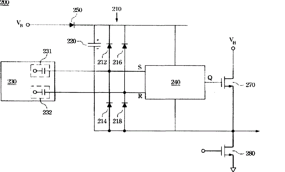
[0033] Please refer to figure 2 , which discloses an equivalent circuit diagram of a high side driver circuit (high side driver) according to an embodiment of the present invention. figure 2 Among them, the high side driving circuit 200 may include a bridge rectifier 210 , a bootstrap capacitor 220 , a signal generator 230 and a latch circuit 240 . The bridge rectifier 210 may include a first diode 212 , a second diode 214 , a third diode 216 and a fourth diode 218 . Wherein, the first diode 212 has a first anode and a first cathode. The second diode 214 has a second anode and a second cathode, wherein the second catho...
PUM
 Abstract
Description
Claims
Application Information