Induction heating device having improved control algorithm and circuit structure

a technology of induction heating and control algorithm, which is applied in the direction of induction heating, electric/magnetic/electromagnetic heating, induction current sources, etc., can solve the problem of not being able to correctly execute the flex mode, the device may not accurately detect whether the object is disposed on the first working coil wc, and the device cannot accurately detect the object when the device is running in the flex mode. the effect of improving the object detection algorithm

Active Publication Date: 2019-11-21
LG ELECTRONICS INC
View PDF0 Cites 1 Cited by
  • Summary
  • Abstract
  • Description
  • Claims
  • Application Information

AI Technical Summary

Benefits of technology

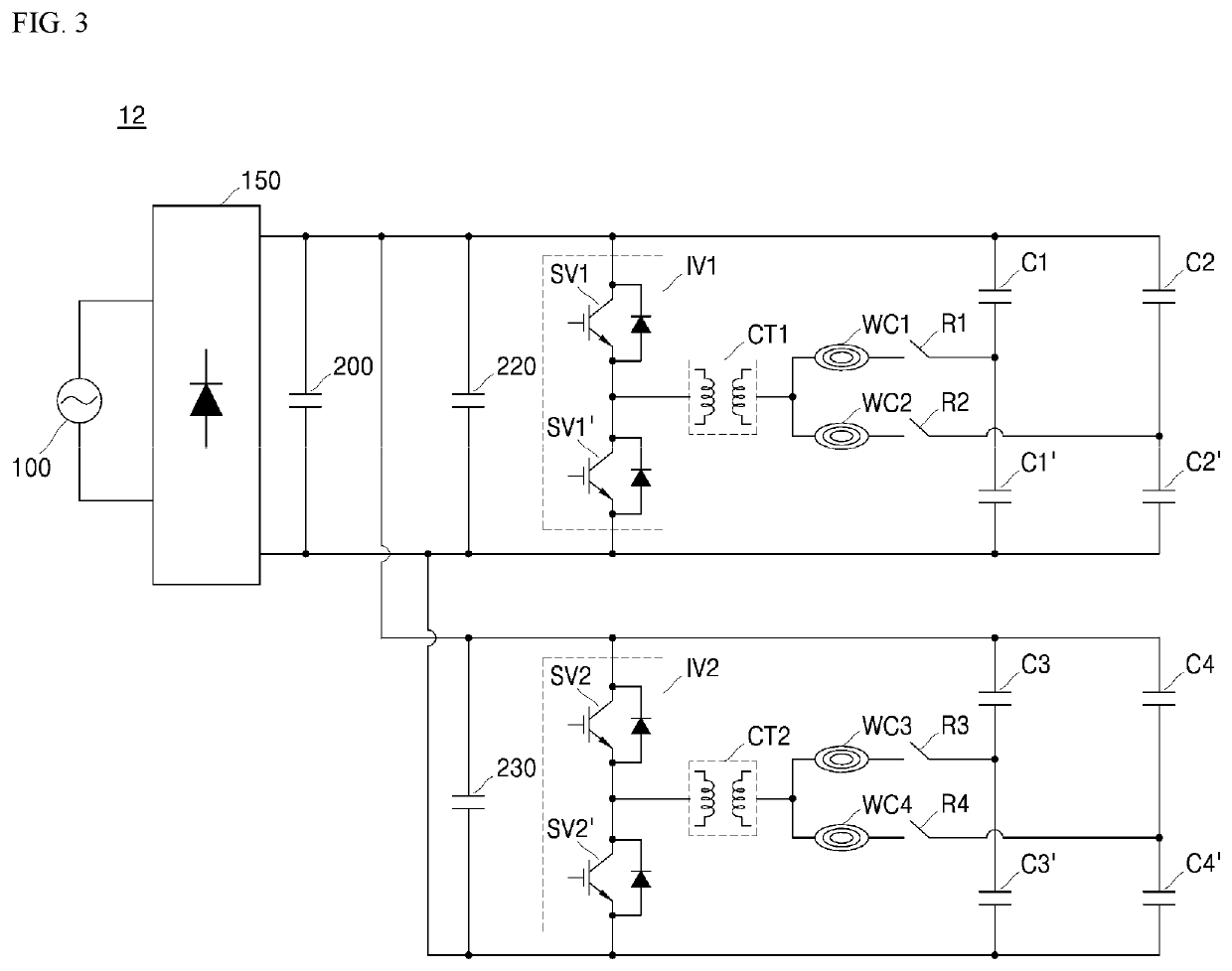
[0023]The induction heating device according to the present disclosure may include a main control unit for determining whether to enable a flex mode, based on an individual coil-based object-detection result for each of the plurality of working coils, and based on a coil set-based object-detection result for a set of the plurality of working coils. This may improve the object-detection algorithm when the device is in the flex mode.
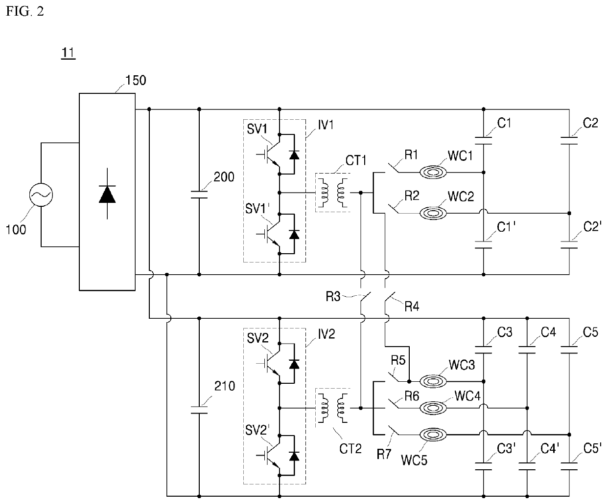
[0024]Further, the induction heating device according to the present disclosure includes a circuit configuration that may invert or switch the direction of the current as is input and output to and from the working coil. This allows the device to improve heating-region control and output control.
[0025]In the induction heating device according to the present disclosure, the object-detection algorithm when the device is ru...

Problems solved by technology

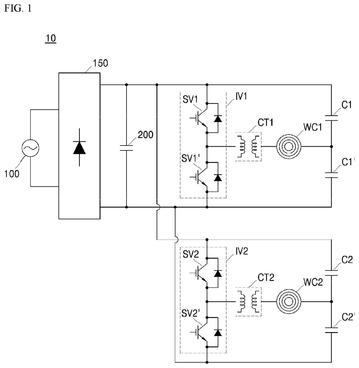
Further, there is no circuit configuration capable of reversing or switching the direction of the current input/output to/from the working coils.
This may lead to a problem that the heated region is concentrated on the edges of the working coils WC1 and WC2 and, hence, the heated region of the object is limited to the region corresponding to the edges of the working coils WC1 and WC2.
Thus, when the object is located on a region corresponding to an area between the first and second working coils WC1 and WC2, the device may not accurately detect whether the object is disposed on the first working coil WC1.
In this case, even when the induction heating device 10 is set to the flex mode, the device cannot correctly execute the flex mode.
In this connection, there is no circuit configuration that allows inverting or switching the direction of the current input and output to and from the working coil.
Thus, for example, when an object is located in a region co...

Method used


Image

  • Induction heating device having improved control algorithm and circuit structure
  • Induction heating device having improved control algorithm and circuit structure
  • Induction heating device having improved control algorithm and circuit structure

Examples


Embodiment Construction

[0035]The above objects, features and advantages will become apparent from the detailed description with reference to the accompanying drawings. Embodiments are described in sufficient detail to enable those skilled in the art in the art to easily practice the technical idea of the present disclosure. Detailed descriptions of well-known functions or configurations may be omitted in order not to unnecessarily obscure the gist of the present disclosure. Hereinafter, embodiments of the present disclosure will be described in detail with reference to the accompanying drawings. Throughout the drawings, like reference numerals refer to like elements.

[0036]FIG. 4 is a circuit diagram showing an induction heating device according to one embodiment of the present disclosure.

[0037]Referring to FIG. 4, an induction heating device 1 according to the present disclosure includes a first board (not shown) having, thereon, a first power supply 100, a first rectifier 150, a first direct-current (DC)...


PUM


Abstract

An induction heating device includes: a first board including a first working coil, a first inverter configured to apply a resonant current to the first working coil, a first current transformer configured to adjusting a magnitude of the first resonant current, a first control unit configured to control the first inverter; and a second board including a second working coil, a second inverter configured to apply a resonant current to the second working coil, a second current transformer configured to adjust a magnitude of the second resonant current, a first relay configured to selectively connect the second working coil to the second current transformer or to the first working coil, a second relay configured to selectively connect the second working coil to the first working coil or to the second resonant capacitor, and a second control unit configure to control the second inverter, the first relay, and the second relay.

Description

CROSS-REFERENCE TO RELATED APPLICATIONS[0001]This application claims the priority of Korean Patent Application No. 10-2018-0056189 filed on May 16, 2018, in the Korean Intellectual Property Office, the disclosure of which is hereby incorporated by reference in its entirety.BACKGROUND1. Technical Field[0002]The present disclosure relates to an induction heating device having an improved control algorithm and an improved circuit structure.2. Description of the Related Art[0003]In homes and restaurants, cooking utensils using various heating methods to heat food are being used. Conventionally, gas ranges using gas as fuel have been widely used. However, in recent years, there has been a spread of devices for heating a cooking vessel such as a loaded object, such as a pot, by using electricity without using gas.[0004]A scheme of heating a loaded object using electricity is divided into a resistive heating type and an inductive heating type. In the electrical resistive heating method, he...

Claims


Application Information

Patent Timeline
IPC IPC(8): H05B6/06H05B6/12
CPCH05B6/1209H05B6/065H05B2213/05H05B6/04
Inventor KWACK, YOUNGHWANSON, SEONGHOYANG, JAEKYUNGLEE, YONGSOO
Owner LG ELECTRONICS INC
Why Eureka
Try Eureka