Control system for thermal module in vehicle

a technology of control system and thermal module, which is applied in the field of climate control, can solve the problems of occupant's back and other pressure points being sweaty, the seat is very hot and uncomfortable for the occupant, and the existing climate control system is not suitable for seats

Active Publication Date: 2009-09-15
GENTHERM INC
View PDF62 Cites 176 Cited by
  • Summary
  • Abstract
  • Description
  • Claims
  • Application Information

AI Technical Summary

Problems solved by technology

For example, an automotive vehicle exposed to the summer weather, where the vehicle has been parked in an unshaded area for a long period, can cause the vehicle seat to be very hot and uncomfortable for the occupant for some time after entering and using the vehicle, even with normal air conditioning.
Furthermore, even with normal air-conditioning, on a hot day, the occupant's back and other pressure points may remain sweaty while seated.
There are, however, drawbacks with existing climate control systems for seats.
For example, some climate control systems are not easily integrated into existing seat construction methods.
Such systems require a significantly greater number of parts as compared to existing automotive seats, and often require complex mechanical parts and / or electrical connections.
In the past, this has resulted in increased costs for individualized occupant cooling in automobiles.
These wires require a significant amount of space and complicate the design and layout of the climate control system.

Method used


Image

  • Control system for thermal module in vehicle
  • Control system for thermal module in vehicle
  • Control system for thermal module in vehicle

Examples


Embodiment Construction

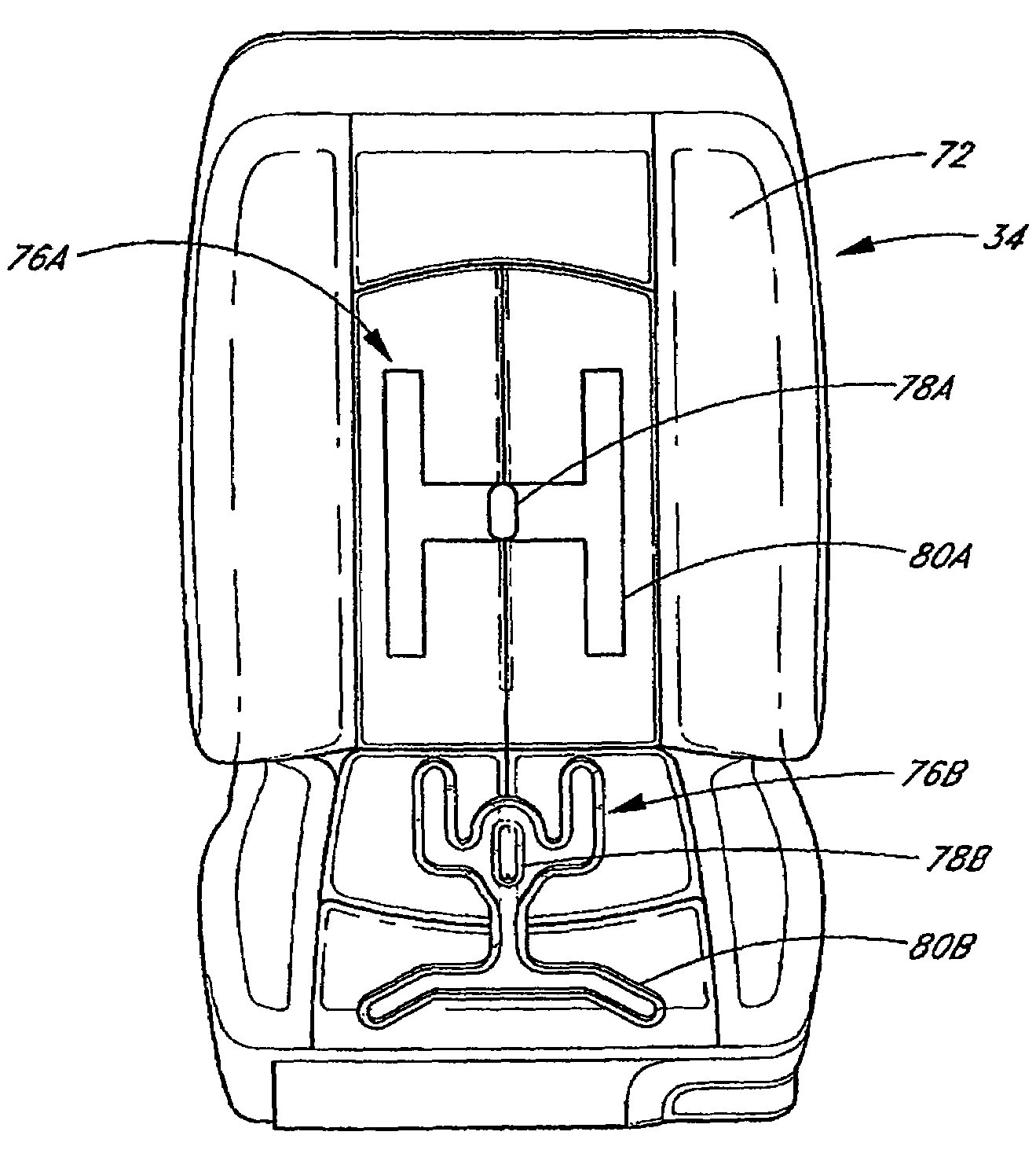
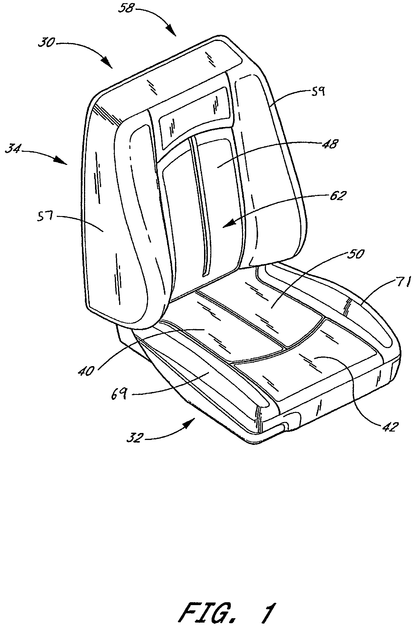
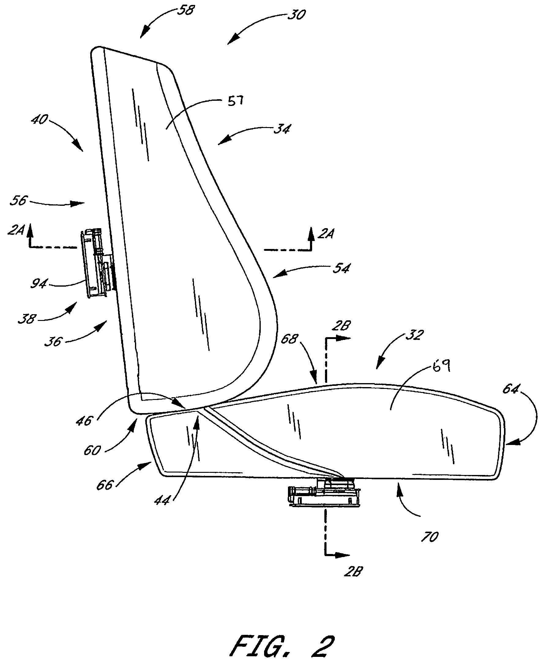
[0025]FIGS. 1 and 2 illustrate an exemplary embodiment of a seat assembly 30 that comprises a seat 32 and a backrest 34. The seat assembly 30 includes a climate control system 36, which will be described in more detail below with reference to FIG. 4.

[0026]When an occupant sits in the seat assembly 30, the occupant's seat is located generally in a seat area 40 of the seat portion 32 and at least a portion of their legs are supported by a thigh area 42 of the seat portion 32. In this embodiment, a rear end 44 of the seat portion 32 is coupled to a bottom end 46 of the backrest portion 34. When the occupant sits in the seat assembly 30, the occupant's back contacts a front surface 48 of the backrest portion 34 and the occupant's seat and legs contact a top surface 50 of the seat portion 32. The surfaces 48, 50 cooperate to support the occupant in a sitting position. The seat assembly 30 can be configured and sized to accommodate occupants of various size and weight.

[0027]In the illustr...


PUM


Abstract

A climate control device includes a first and a second thermal module. The first module is configured to provide climate conditioned air to a first portion of a seat. The second module is configured to provide climate conditioned air to a second portion of the seat. A control system is provided for controlling the climate control device. The control system includes an input device for providing a set point for the system. A first control unit of the control system is provided for the first thermal module and a second control unit is provided for the second thermal module.

Description

PRIORITY INFORMATION[0001]This application claims the priority benefit under 35 U.S.C. § 119(e) of Provisional Application 60 / 637,725, filed Dec. 20, 2004.BACKGROUND OF THE INVENTION[0002]1. Field of the Invention[0003]This invention relates to climate control. More specifically, this invention relates to climate control of a seat.[0004]2. Description of the Related Art[0005]Temperature modified air for environmental control of living or working space is typically provided to relatively extensive areas, such as entire buildings, selected offices, or suites of rooms within a building. In the case of vehicles, such as automobiles, the entire vehicle is typically cooled or heated as a unit. There are many situations, however, in which more selective or restrictive air temperature modification is desirable. For example, it is often desirable to provide an individualized climate control for an occupant seat so that substantially instantaneous heating or cooling can be achieved. For examp...

Claims


Application Information

Patent Timeline
Patent Type & Authority Patents(United States)
IPC IPC(8): F25B21/02
CPCA47C7/74B60H1/00285B60N2/5635B60H1/2218B60N2/5657B60N2/5692B60N2/5614B60H1/00478B60N2/5642B60H2001/003
Inventor PETROVSKI, DUSKO
Owner GENTHERM INC
Why Eureka
Try Eureka