
Windpark turbine control system and method for wind condition estimation and performance optimization

a control system and wind turbine technology, applied in process and machine control, electric generator control, instruments, etc., can solve problems such as imposing limits on how much power, and achieve the effects of reducing speed, minimizing load impact thereon, and reducing load impa

Inactive Publication Date: 2007-05-31
GENERAL ELECTRIC CO
View PDF12 Cites 186 Cited by
  • Summary
  • Abstract
  • Description
  • Claims
  • Application Information

AI Technical Summary

Benefits of technology

[0004] The above-outlined known approach of monitoring and communicating wind conditions to a downstream turbine and reducing the power output in case of high wind velocities makes it possible, for example, in a variable-speed pitch plant with a control algorithm for controlling the rotor speed and / or pitch angle averaged over time, to obtain high ratios between the rotor diameter and the generator performance without an accompanying increase in component fatigue as compared to conventionally designed turbines.
[0009] Thus, the invention may be embodied in a control system for a windpark power plant including plurality of wind turbines, said system comprising a central processing and control unit operatively coupled to said wind turbines to receive data from and transmit at least one of data and control signals to each said wind turbine, said central processing and control unit processing data received from at least one upstream turbine to predict a load impact on turbines downstream thereof, and selectively generating and transmitting control signals to at least one of (1) reduce power of at least one downstream wind turbine to minimize load impact and / or (2) reduce a speed of at least one said upstream turbine to reduce fatigue load and increase power capture in at least one downstream turbine.

Problems solved by technology

However, this is not addressed by the '821 patent approach.
Furthermore, recently, because in certain areas there are a large number of wind farms close together and because of the nature of wind and the fact that it fluctuates electricity utilities have started to impose restrictions on windparks.
For example, utilities may impose limits on how much power an operating wind farm can produce, or may dictate a slower start-up, etc.

Method used


Image

  • Windpark turbine control system and method for wind condition estimation and performance optimization
  • Windpark turbine control system and method for wind condition estimation and performance optimization
  • Windpark turbine control system and method for wind condition estimation and performance optimization

Examples


Embodiment Construction

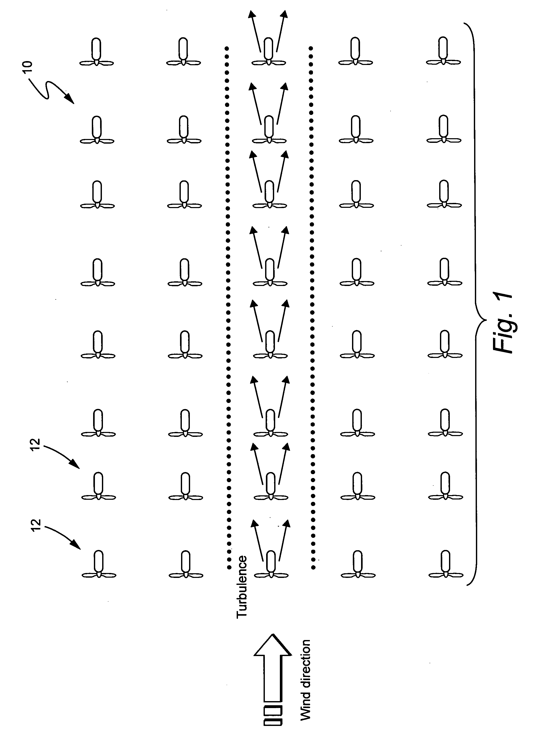
[0016] Referring to FIG. 1, a windpark 10 is schematically depicted comprising a plurality of wind turbines 12. For convenience of explanation, the windpark is depicted as having evenly spaced rows of wind turbines although it is to be understood that more or fewer turbines may be provided and that the turbines may be distributed in varying patterns or arrays depending upon the topography, prevailing wind direction, and the like.

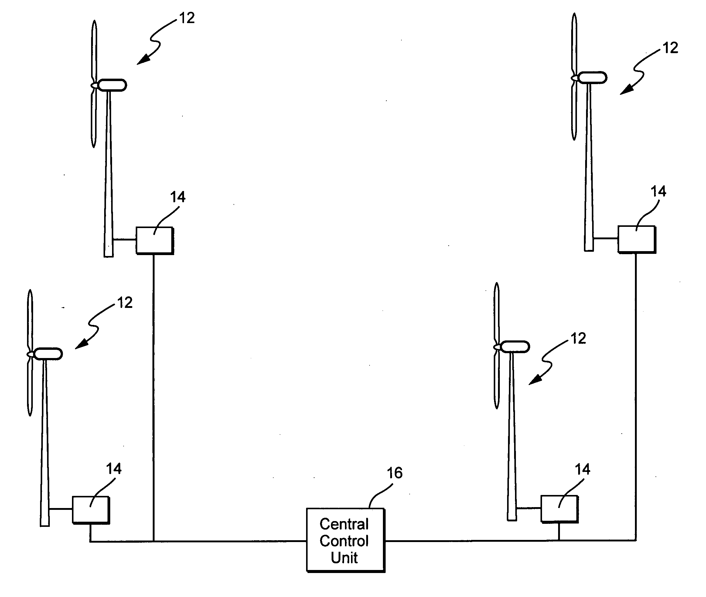
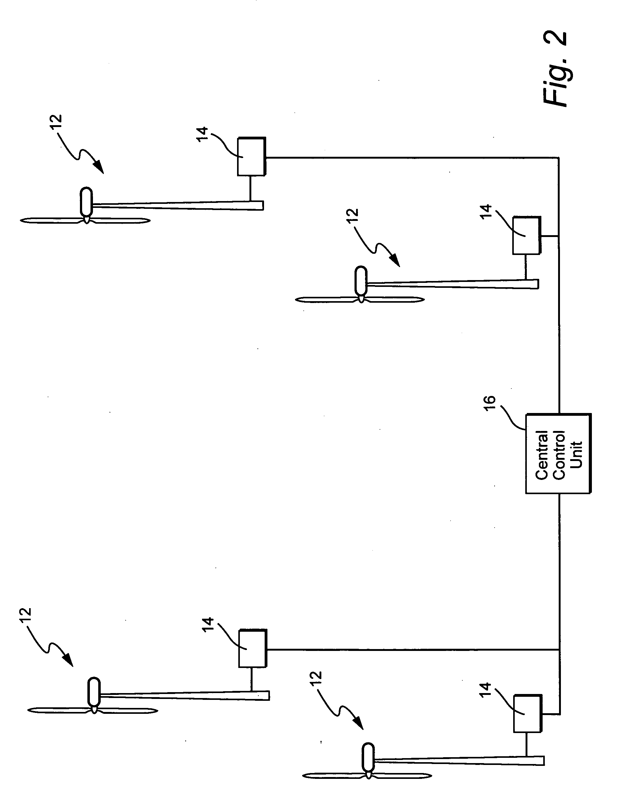
[0017] As schematically shown in FIG. 2, each of the wind turbines 12 has a respective controller 14 which receives signals regarding wind direction, velocity, load and the like and controls the respective turbine accordingly. More particularly, the tower controllers are conventionally provided to receive and act upon local sensor information for the respective turbine tower. Each wind turbine tower has associated with it input values which are locally detected by measurement sensors such as the rotor and generator speeds, the electrical power, the generato...


PUM


Abstract

A method and system for controlling a windpark power plant includes a central processing and control unit operatively coupled to wind turbines in the windpark to receive data from and selectively transmit at least one of data and control signals to each wind turbine, to reduce fatigue loads and comply with power limits.

Description

BACKGROUND OF THE INVENTION [0001] The invention relates to the operation and control of a large group of wind turbines arranged as a windpark. [0002] As is widely known, the largest part of the high stresses that tend to shorten the life span of a wind turbine will occur at high wind velocities. According to known approaches for reducing stresses on the rotor, nacelle, tower and foundation, the rotational speed of the rotor of a wind turbine and the power output of the turbine can be decreased in the case of high wind velocity. [0003] Wind turbines are conventionally equipped with measurement systems and control systems to enable them to independently react to changing wind conditions. These systems are designed to maximize energy capture while minimizing the impact of fatigue and extreme loads. The effectiveness of these control systems is constrained by limitations on sensor technologies. In this regard, measurement systems and detectors local to the particular wind turbine neces...

Claims


Application Information

Patent Timeline
Patent Type & Authority Applications(United States)
IPC IPC(8): F03D9/00
CPCF03D7/0224F03D7/0276F03D7/0292F03D7/048F05B2240/96F05B2260/70F05B2260/821F05B2270/101F05B2270/1095F05B2270/32F05B2270/321F05B2270/328F05B2270/329F05B2270/331F05B2270/335Y02E10/723F05B2270/204Y02E10/72
Inventor SCHRAM, CHRISTIANVYAS, PARAG
Owner GENERAL ELECTRIC CO
Learn More