Method for forming a planar mirror using a sacrificial oxide

a technology of sacrificial oxide and planar mirror, which is applied in the direction of photomechanical equipment, instruments, originals for photomechanical treatment, etc., can solve the problems of providing an unacceptably low planar surface percentage of the mirror plate for reliable reflection, and the proportion of the deformed mirror plate that is distorted to provide an attachment point of similar siz

Inactive Publication Date: 2006-02-02
HEWLETT PACKARD DEV CO LP
View PDF1 Cites 52 Cited by
  • Summary
  • Abstract
  • Description
  • Claims
  • Application Information

AI Technical Summary

Benefits of technology

[0008] The micro-mirror device includes a mirror plate that is configured to be planar across its entire reflective surface using the fabrication techniques as described herein. This disclosure thereby provides a technique by which the entire reflective surface of the micro-mirror device provides a reliable reflection of light in a desired direction.

Problems solved by technology

As the dimensions of the mirror plate decreases, the corresponding percentage of the deformed mirror plate that is distorted to provide for an attachment point of similar size become unacceptably high.
As such, many smaller mirror plates provide an unacceptably low planar surface percentage of the mirror plate for reliable reflection.

Method used


Image

  • Method for forming a planar mirror using a sacrificial oxide
  • Method for forming a planar mirror using a sacrificial oxide
  • Method for forming a planar mirror using a sacrificial oxide

Examples


example micro

[0010] Example Micro-Mirror Device

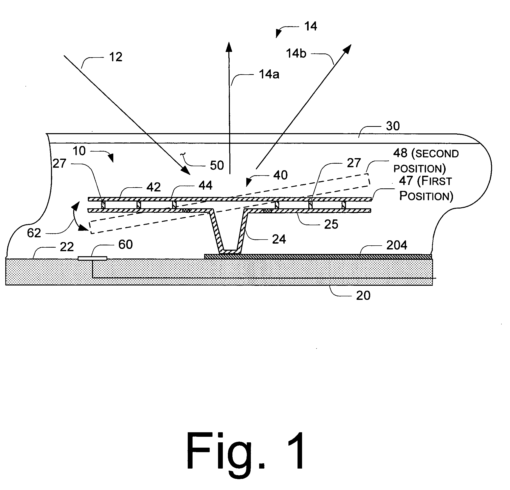
[0011] With reference to FIG. 1, the micro-mirror device 10 is formed on a substrate 20 and lies underneath a coverplate 30. One embodiment of the micro-mirror device 10 comprises at least some of an actuator element 40, a support 24, a hinged member 25, the mirror plate 42, a plurality of mirror support elements 27, and an electrode 60. The actuator element 40 acts as a micro-actuator that utilizes electrical to mechanical conversion to generate a force and cause movement or actuation of the mirror plate 42 relying on the flexibility of the hinged member 25. The hinged member 25 is formed with one or more hinges (shown in checkered cross-section in FIG. 1) that allow the hinged member 25 to be displaced during actuation. In the illustrated and described embodiment, the mirror plate 42 is angularly displaceable from a first position 47 that is substantially parallel to a surface of the substrate 20 to a second position as a result of displacement of...


PUM


Abstract

A micro electromechanical system (MEMS) mirror, comprising a displaceable hinged member, a mirror plate, and a plurality of mirror support elements. The mirror plate has a planar mirror face affixed thereto. The plurality of mirror support elements extend between the displaceable hinged member and the mirror plate.

Description

BACKGROUND OF THE INVENTION [0001] With a micro-mirror device, which is one type of micro electromechanical (MEMS) device, an actuator controllably displaces a mirror plate to reflect incident light in a controllable fashion. Micro-mirror devices can be used in a number of optical devices such as optical projectors, optical displays, and / or for optical communication devices. Multiple micro-mirror devices are arranged in an array in which each micro-mirror device provides one pixel for use in the display, or one bit for use in the communication device. [0002] With many micro-mirror devices, the mirror plate attaches to the actuator at an attachment point. The surface of the mirror plate is distorted at the attachment point to allow for the attachment. Such distorted areas reflect light in unpredictable directions. As the dimensions of the mirror plate decreases, the corresponding percentage of the deformed mirror plate that is distorted to provide for an attachment point of similar s...

Claims


Application Information

Patent Timeline
Patent Type & Authority Applications(United States)
IPC IPC(8): G02B26/08
CPCG02B26/0841
Inventor NIKKEL, ERIC L.MONROE, MICHAEL G.SZEPESI, MICKEY
Owner HEWLETT PACKARD DEV CO LP
Why Eureka
Try Eureka