Torsional nonresonant z-axis micromachined gyroscope with non-resonant actuation to measure the angular rotation of an object

a micro-machined gyroscope and z-axis technology, applied in the direction of acceleration measurement using interia forces, instruments, devices using electric/magnetic means, etc., can solve the problems of restricting the performance of the gyroscope, limiting the actuation amplitude of the gyroscope, and limiting the actuation voltage. , to achieve the effect of minimizing the nonlinear force profile and instability, reducing

Inactive Publication Date: 2006-02-16
RGT UNIV OF CALIFORNIA
View PDF2 Cites 83 Cited by
  • Summary
  • Abstract
  • Description
  • Claims
  • Application Information

AI Technical Summary

Benefits of technology

[0013] The illustrated embodiment is a surface-micromachined torsional gyroscope design utilizing dynamical amplification of rotational oscillations to achieve large oscillation amplitudes about the drive axis without resonance; thus addressing the issues of electrostatic instability while providing large sense capacitance. The approach employs a three-mass structure with two gimbals and a sensing plate. Large oscillation amplitudes in the passive gim...

Problems solved by technology

However, the limited thickness of structural layers attained in current surface-micromachining processes results in very small sensing capacitances and higher actuation voltages, restricting the performance of the gyroscope.
However, highly nonlinear and unstable nature of parallel-plate actuation limits the actuation amplitude of the gyroscope.
However, especially for lightly-damped devices, the requirement for mode-matching is well beyond fabrication tolerances; and none of the symmetric designs can provide the required degree of mode-matching without feedback control.
Thus, surface-micro machined implementations use very thin actuation and detection electrode finge...

Method used


Image

  • Torsional nonresonant z-axis micromachined gyroscope with non-resonant actuation to measure the angular rotation of an object
  • Torsional nonresonant z-axis micromachined gyroscope with non-resonant actuation to measure the angular rotation of an object
  • Torsional nonresonant z-axis micromachined gyroscope with non-resonant actuation to measure the angular rotation of an object

Examples


Embodiment Construction

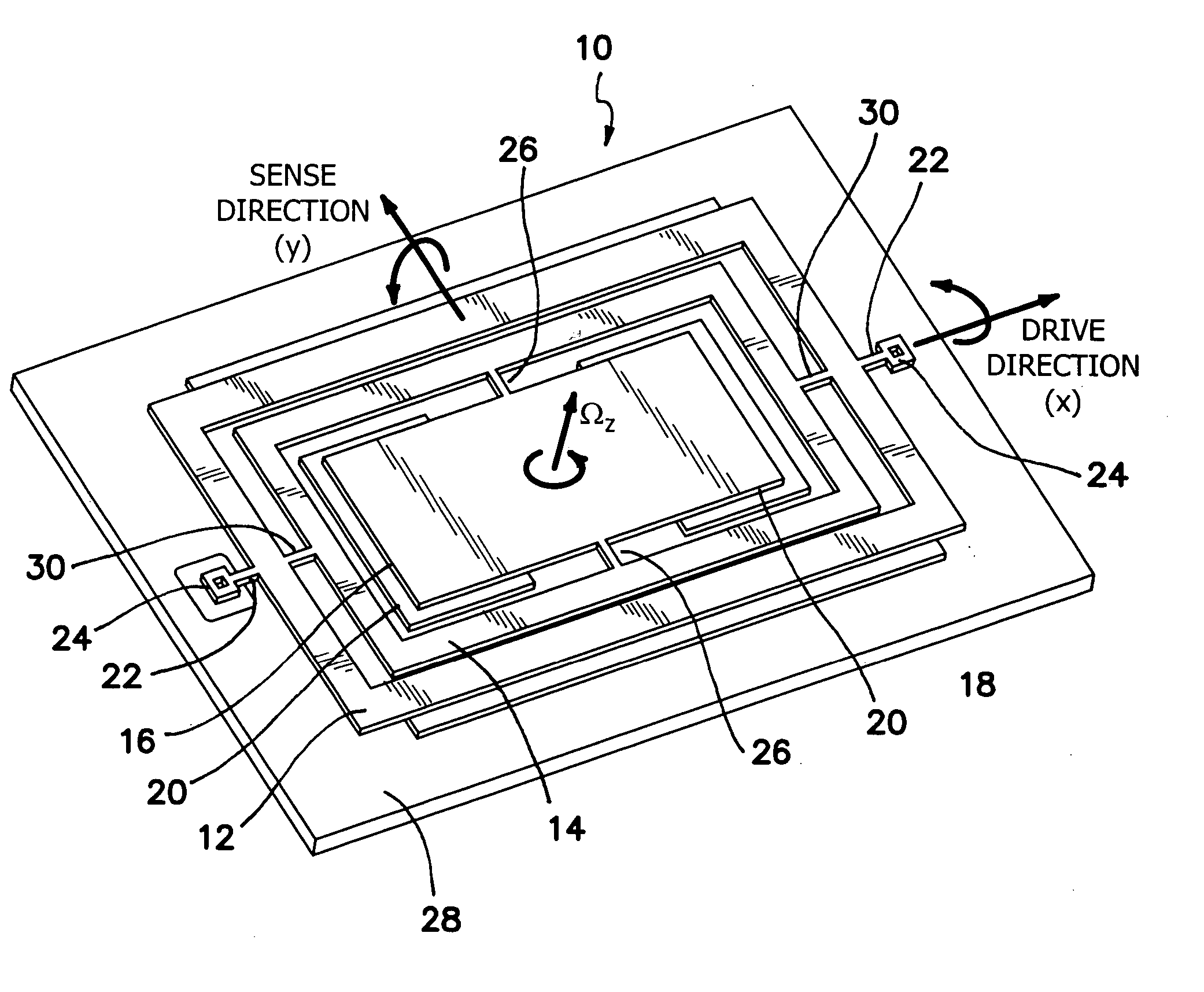
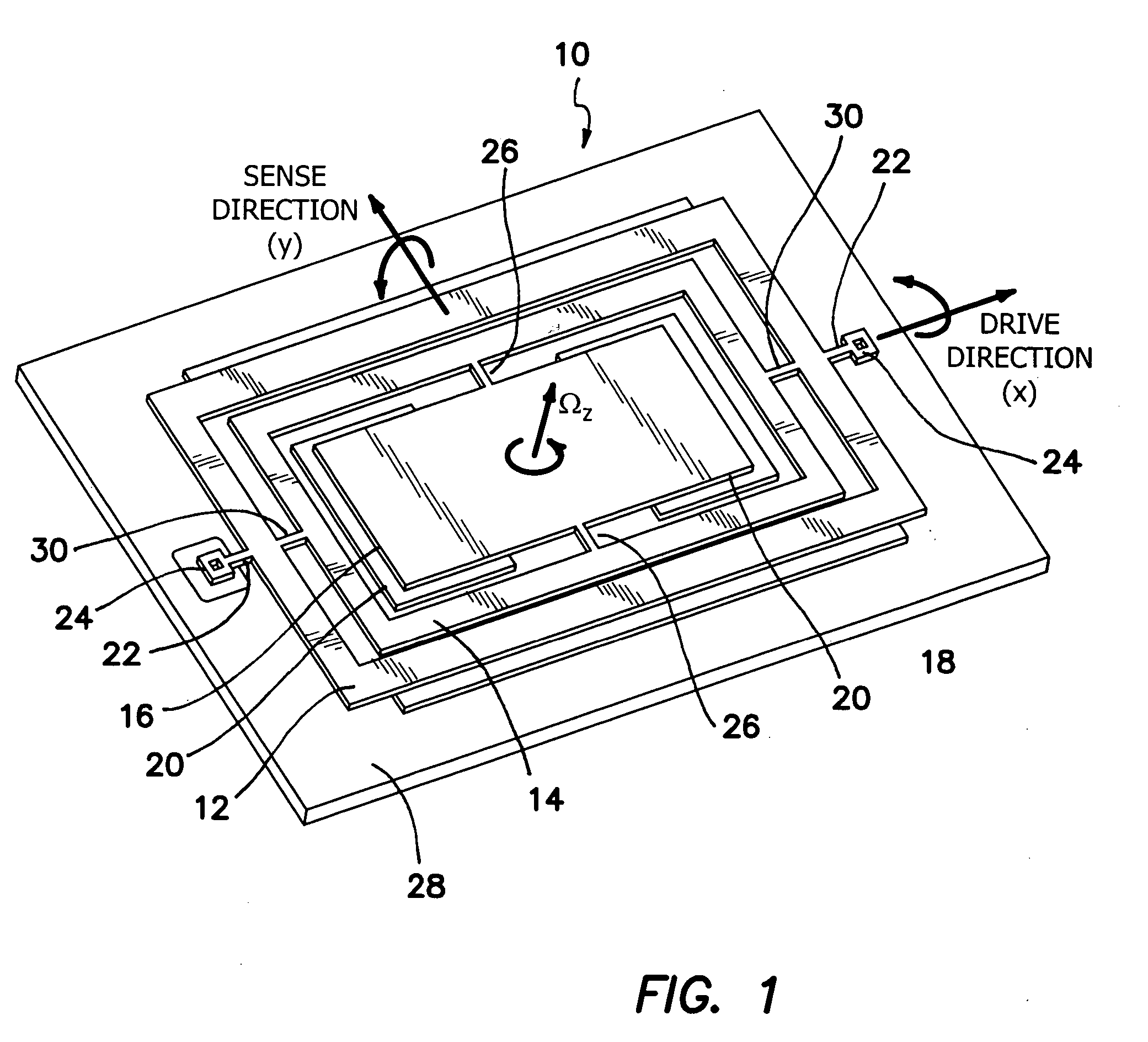
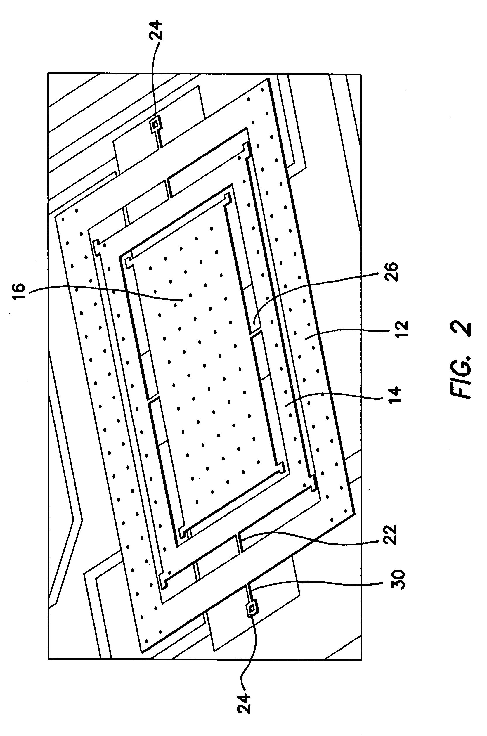
[0029] The illustrated embodiment of torsional gyroscope system, generally denoted by reference numeral 10, is comprised of three interconnected rotary masses: the active gimbal 12, the passive gimbal 14, and the sensing plate 16 as depicted in FIG. 1. The active gimbal 12 and the passive gimbal 14 are free to oscillate only about the drive axis x. The sensing plate 16 oscillates together with the passive gimbal 14 about the drive axis, x, but is free to oscillate independently about the sense axis y, which is the axis of response when a rotation along z-axis is applied. Active gimbal 12 is coupled to substrate 28 though opposing anchors 24 lying along the x direction and held above substrate 28 by a pair of opposing suspension beams 22. Similarly, a pair of suspension beams 30 lying along the x direction connect active gimbal 12 to passive gimbal 14. Passive gimbal 14 is connected to sensing gimbal 16 by a pair of opposing suspension beams 26 lying along the y direction.

[0030] The...


PUM


Abstract

A gimbal-type torsional z-axis micromachined gyroscope with a non-resonant actuation scheme measures angular rate of an object with respect to the axis normal to the substrate plane (the z-axis). A 2 degrees-of-freedom (2-DOF) drive-mode oscillator is comprised of a sensing plate suspended inside two gimbals. By utilizing dynamic amplification of torsional oscillations in the drive-mode instead of resonance, large oscillation amplitudes of the sensing element is achieved with small actuation amplitudes, providing improved linearity and stability despite parallel-plate actuation. The device operates at resonance in the sense direction for improved sensitivity, while the drive direction amplitude is inherently constant within the same frequency band.

Description

RELATED APPLICATIONS [0001] The present application is related to U.S. Provisional Patent Application, Ser. No. 60 / 602,237, filed on Aug.16, 2004, which is incorporated herein by reference and to which priority is claimed pursuant to 35 USC 119.BACKGROUND OF THE INVENTION [0002] 1. Field of the Invention [0003] The invention relates to the field of inertial micromachined transducers for measurement of angular rotation rate of an object. [0004] 2. Description of the Prior Art [0005] Micromachined gyroscopes have a wide application range, including high performance navigation and guidance systems, automotive safety systems like yaw and tilt control, roll-over protection and next generation airbag and antilock brake systems, and also consumer electronics applications like image stabilization in video cameras, virtual reality products, and pointing devices. Also, orders of magnitude reduction in production cost is achieved by surface micromachining. [0006] Many emerging angular-rate mea...

Claims


Application Information

Patent Timeline
IPC IPC(8): G01P9/04G01P1/04
CPCG01C19/5719
Inventor ACAR, CENKSHKEL, ANDREI M.
Owner RGT UNIV OF CALIFORNIA
Why Eureka
Try Eureka