Blade tension gauge

a tension gauge and blade technology, applied in band saws, metal sawing accessories, manufacturing tools, etc., can solve the problems of blade breakage, premature failure, and load that is too low, and achieves the effect of reducing the number of blades

Active Publication Date: 2006-02-23
SNODGRASS JR HOWARD L
View PDF31 Cites 11 Cited by
  • Summary
  • Abstract
  • Description
  • Claims
  • Application Information

AI Technical Summary

Benefits of technology

[0006] It is an object of this invention to provide the end user with a constant reading o...

Problems solved by technology

Loads that are too low do not provide adequate stiffness to the blade.
Loads that are too high can cause blade breakage and premature failure.
These methods are notoriously inaccurate and make it difficult to consistently set just the right tension for best performance and longest blade life.
Such gauges d...

Method used


Image

  • Blade tension gauge
  • Blade tension gauge
  • Blade tension gauge

Examples


Embodiment Construction

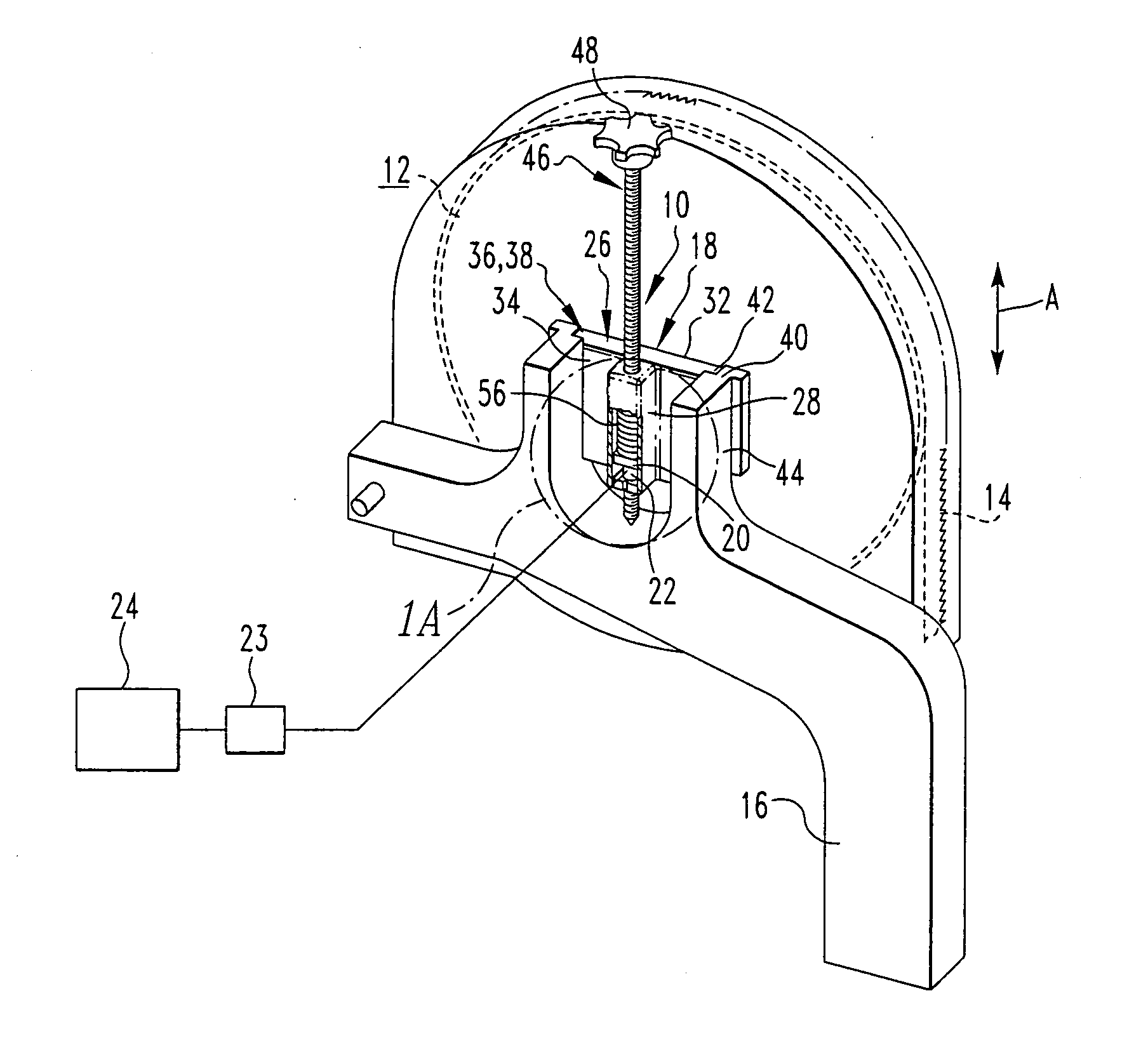
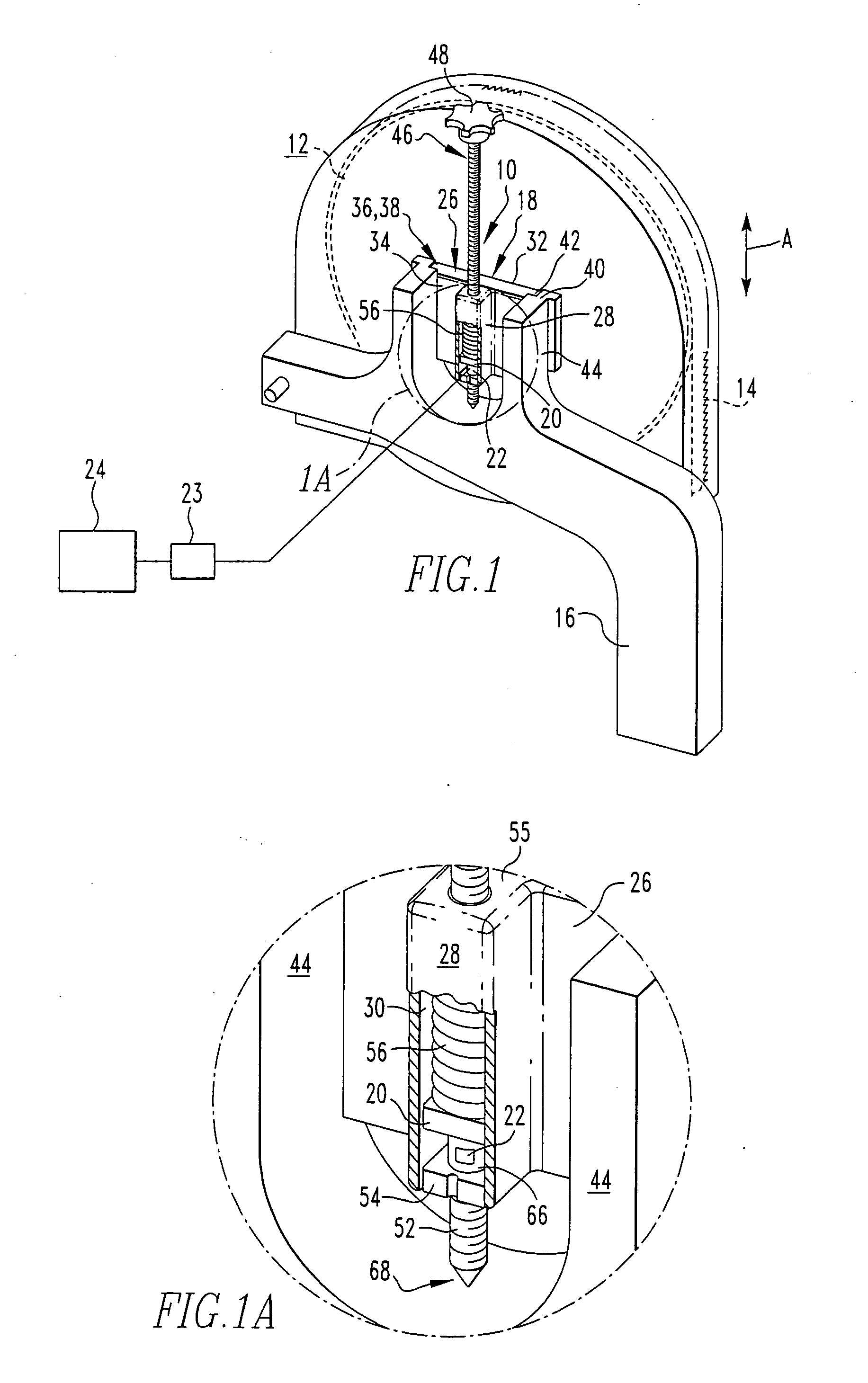
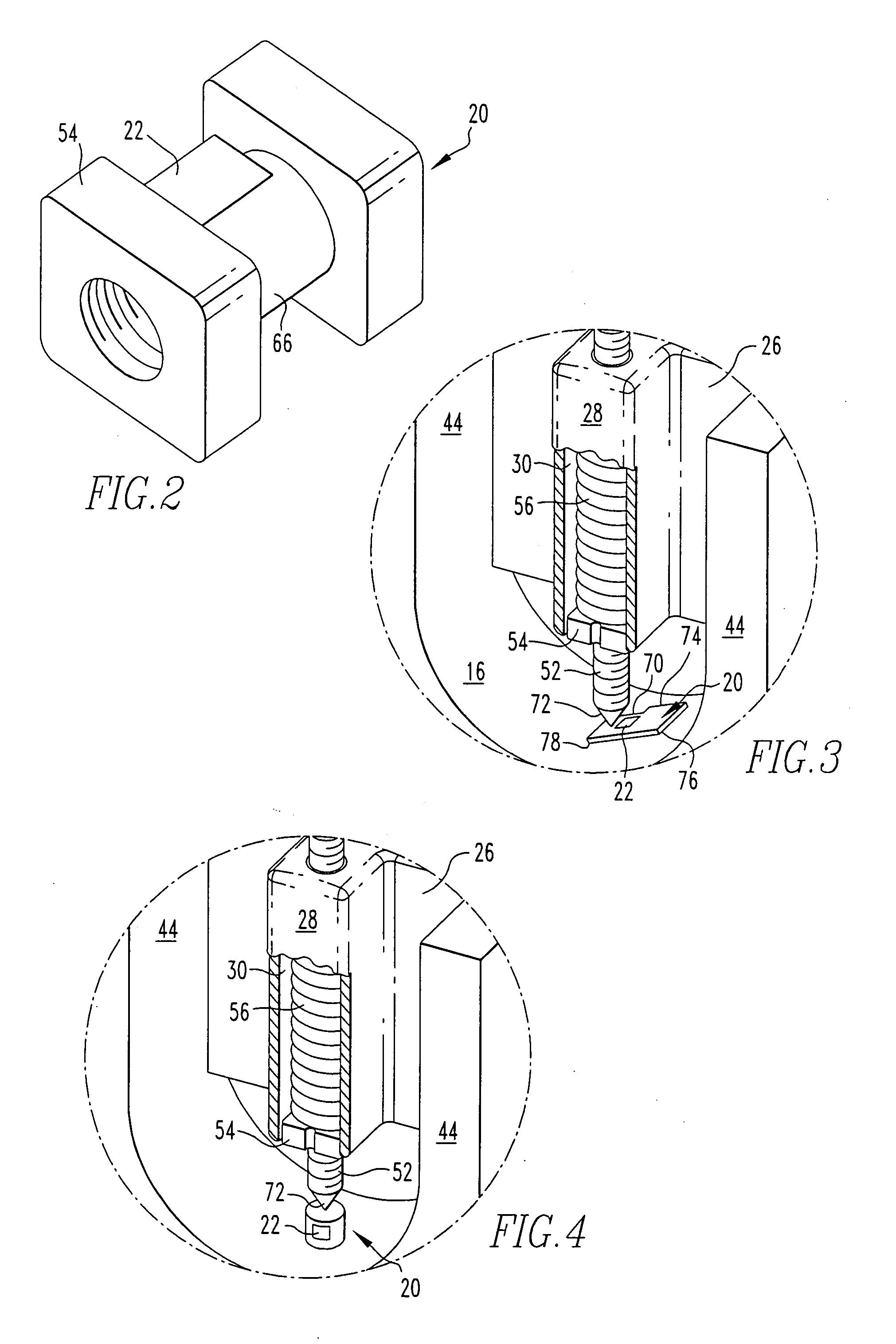
[0022] A complete understanding of the invention will be obtained from the following description when taken in connection with the accompanying drawing figures wherein like reference characters identify like parts throughout.

[0023] For purposes of the description hereinafter, the terms “upper”, “lower”, “right”, “left”, “vertical”, “horizontal”, “top”, “bottom”, and derivatives thereof shall relate to the invention as it is oriented in the drawing figures. However, it is to be understood that the invention may assume various alternative variations and step sequences, except where expressly specified to the contrary. It is also to be understood that the specific devices and processes illustrated in the attached drawings, and described in the following specification, are simply exemplary embodiments of the invention. Hence, specific dimensions and other physical characteristics related to the embodiments disclosed herein are not to be considered as limiting.

[0024] Referring to FIGS....


PUM

PropertyMeasurementUnit
Pressureaaaaaaaaaa
Mechanical propertiesaaaaaaaaaa
Tensionaaaaaaaaaa

Abstract

Disclosed is a blade tension gauge for a band saw which provides a constant reading of the magnitude of the forces that act to put tension on the blade. The band saw includes a moveable wheel, a blade, and a frame, where movement of the moveable wheel in relation to the frame tensions the blade. The blade tension gauge includes a wheel positioning assembly rigidly connected to the moveable wheel and connected to the frame to be moveable relative to the frame. A load element is positioned to receive a load existing between the wheel positioning assembly and the frame. A sensor is configured to measure the load. A display is configured to display the tension value. Also disclosed is a method for outputting the tension of the blade of a band saw.

Description

BACKGROUND OF THE INVENTION [0001] 1. Field of the Invention [0002] The present invention is directed to blade tension gauges for band saws and the like. [0003] 2. Description of Related Art [0004] In order to cut properly, the blade of a band saw must be pre-tensioned to an adequate degree so that the blade can more easily resist any twisting or sideways movement during cutting. Blades of different sizes require different loads to achieve this state. Loads that are too low do not provide adequate stiffness to the blade. Loads that are too high can cause blade breakage and premature failure. Current practice for many users is to adjust the blade tension “by ear”, that is to apply load until the tension “feels right” in terms of the sound the blade makes and the way it performs. Another practice is to physically push on the blade to deform the blade. The degree of deflection of the blade is used as an indication of the blade tension. Yet another practice is to install a spring in the...

Claims


Application Information

Patent Timeline
IPC IPC(8): B26D1/00B26D1/46
CPCB23D55/10B26D1/48B23D59/001Y10T83/089Y10T83/7251Y10T83/7239Y10T83/04Y10T83/7226Y10T83/722Y10T83/175Y10T83/7151
Inventor SNODGRASS, HOWARD J. JR.
Owner SNODGRASS JR HOWARD L
Why Eureka
Try Eureka