

Electro-optical device and electronic apparatus
a technology of optical devices and electronic devices, applied in the direction of deaf-aid sets, electrical transducers, transducer details, etc., can solve the problems of large volume of piezoelectric vibrating bodies, inability to achieve sufficient reduction in size or thickness of the case, etc., to achieve the effect of reducing manufacturing costs, reducing the number of parts, and further reducing the size and thickness of the optical devi
- Summary
- Abstract
- Description
- Claims
- Application Information
AI Technical Summary
Benefits of technology
Problems solved by technology
Method used
Image

Examples
first embodiment
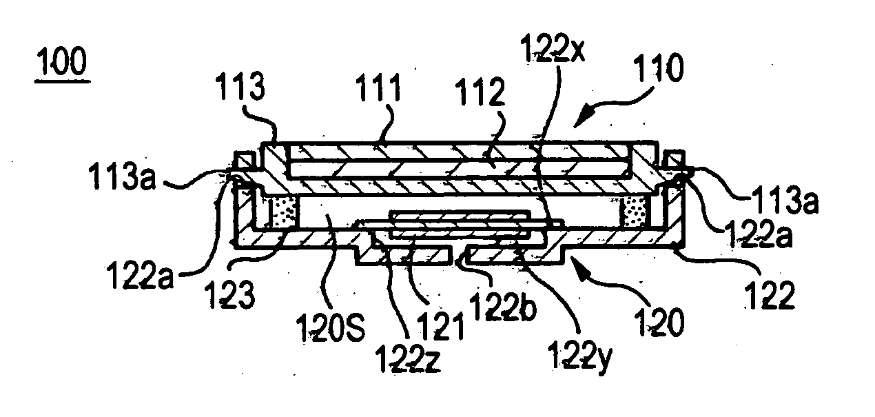
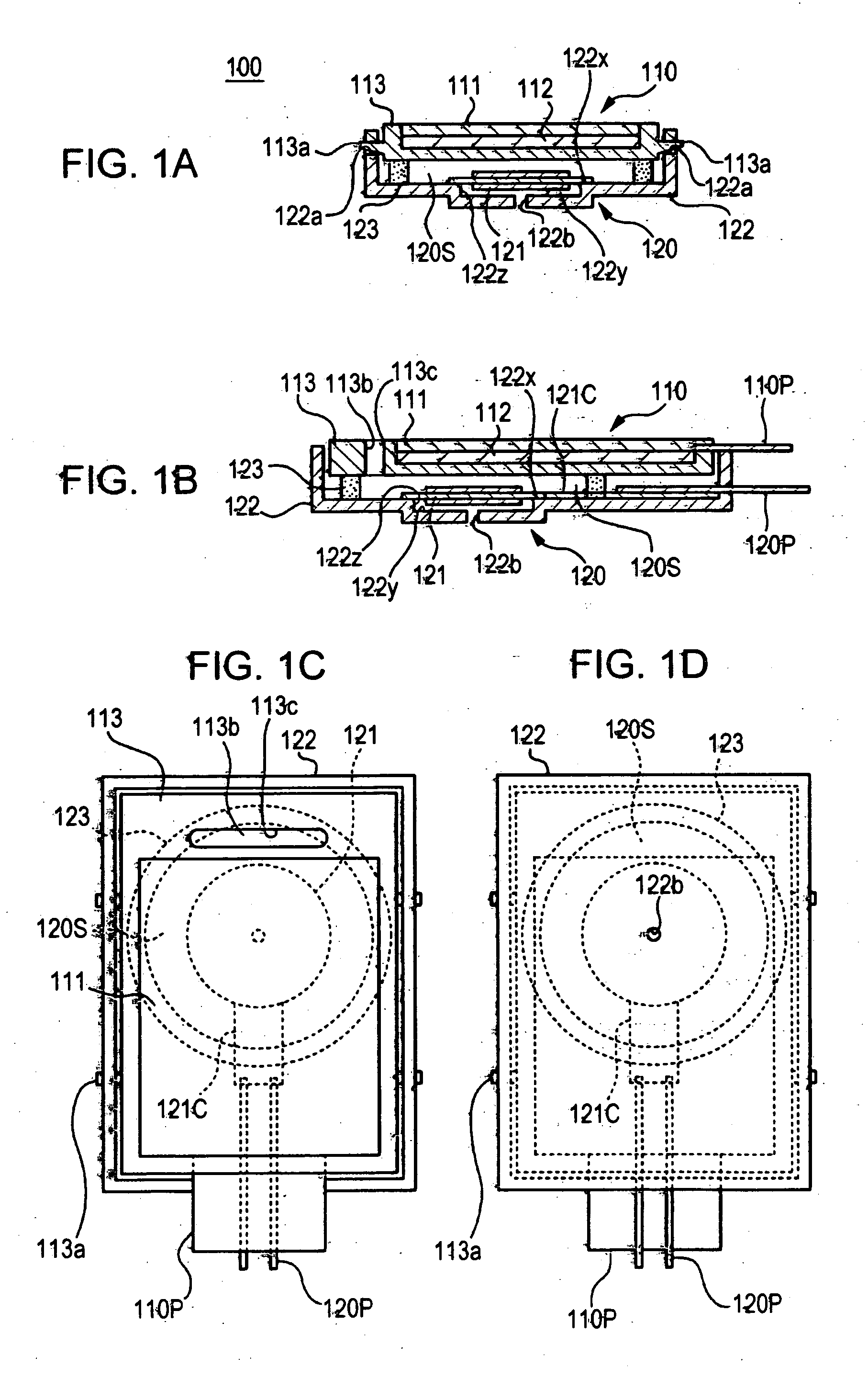
[0037]FIG. 1A is a cross-sectional view taken along one direction (short-side direction) of an electro-optical device 100 according to the invention. FIG. 1B is a cross-sectional view taken along the other direction (long-side direction) of the electro-optical device 100. FIG. 1C is a plan view showing the electro-optical device 100. FIG. 1D is a bottom view showing the electro-optical device 100. The electro-optical device 100 includes a display section 110 that has an electro-optical panel 111 and a sound-production section 120 that has a sound-production vibrating body 121.
[0038] The electro-optical panel 111 is constituted by anyone of various electro-optical panels, such as a liquid crystal display panel, an organic electroluminescent panel, a plasma display panel, a field emission panel, and the like. In the present specification, it is assumed that a liquid crystal display panel is used. A backlight 112 that illuminates the electro-optical panel 111 from the back is disposed...
second embodiment
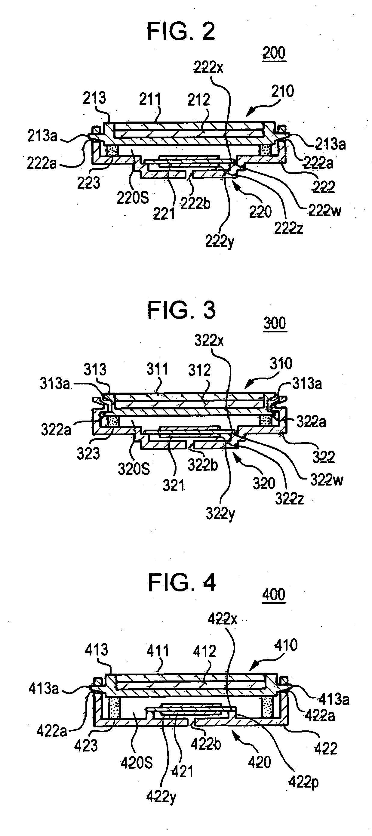
[0054] Next, a second embodiment according to the invention will be described with reference to FIG. 2. FIG. 2 is a cross-sectional view taken along one direction (short-side direction) of the electro-optical device 200 according to the second embodiment of the invention. Other parts, which are not shown in FIG. 2, can be constituted similarly to those in the above-described first embodiment and thus the descriptions thereof will be omitted.
[0055] The electro-optical device 200 of this embodiment includes a display section 210 having an electro-optical panel 211 and a sound-production section 220 having a sound-production vibrating body 221. Here, the electro-optical panel 211, a backlight 212, a panel-holding frame 213, the sound-production vibrating body 221, and a support member 223 are the same as those in the first embodiment and thus the descriptions thereof will be omitted.
[0056] In a sound-production frame 222 of the present embodiment, a fixed inner surface portion 222x t...
third embodiment
[0057] Next, a third embodiment according to the invention will be described with reference to FIG. 3. FIG. 3 is a cross-sectional view taken along one direction (short-side direction) of an electro-optical device 300 according to the third embodiment of the invention. In the present embodiment, other parts, which are not shown in FIG. 3, can be constituted similarly to those in the above-described first embodiment and thus the descriptions thereof will be omitted.
[0058] The electro-optical device 300 of this embodiment includes a display section 310 having an electro-optical panel 311 and a sound-production section 320 having a sound-production vibrating body 321. Here, the electro-optical panel 311, a backlight 312, the sound-production vibrating body 321, and a support member 323 are the same as those in the-second embodiment and thus the descriptions thereof will be omitted.
[0059] In this embodiment, a panel-holding frame 313 and a sound-production frame 322 are substantially ...
PUM
 Abstract
Description
Claims
Application Information