

Embroidery machine and embroidery system
- Summary
- Abstract
- Description
- Claims
- Application Information
AI Technical Summary
Problems solved by technology
Method used
Image

Examples
Embodiment Construction
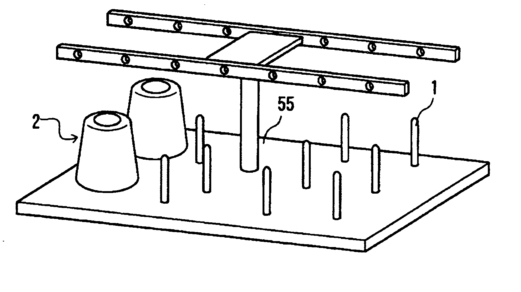
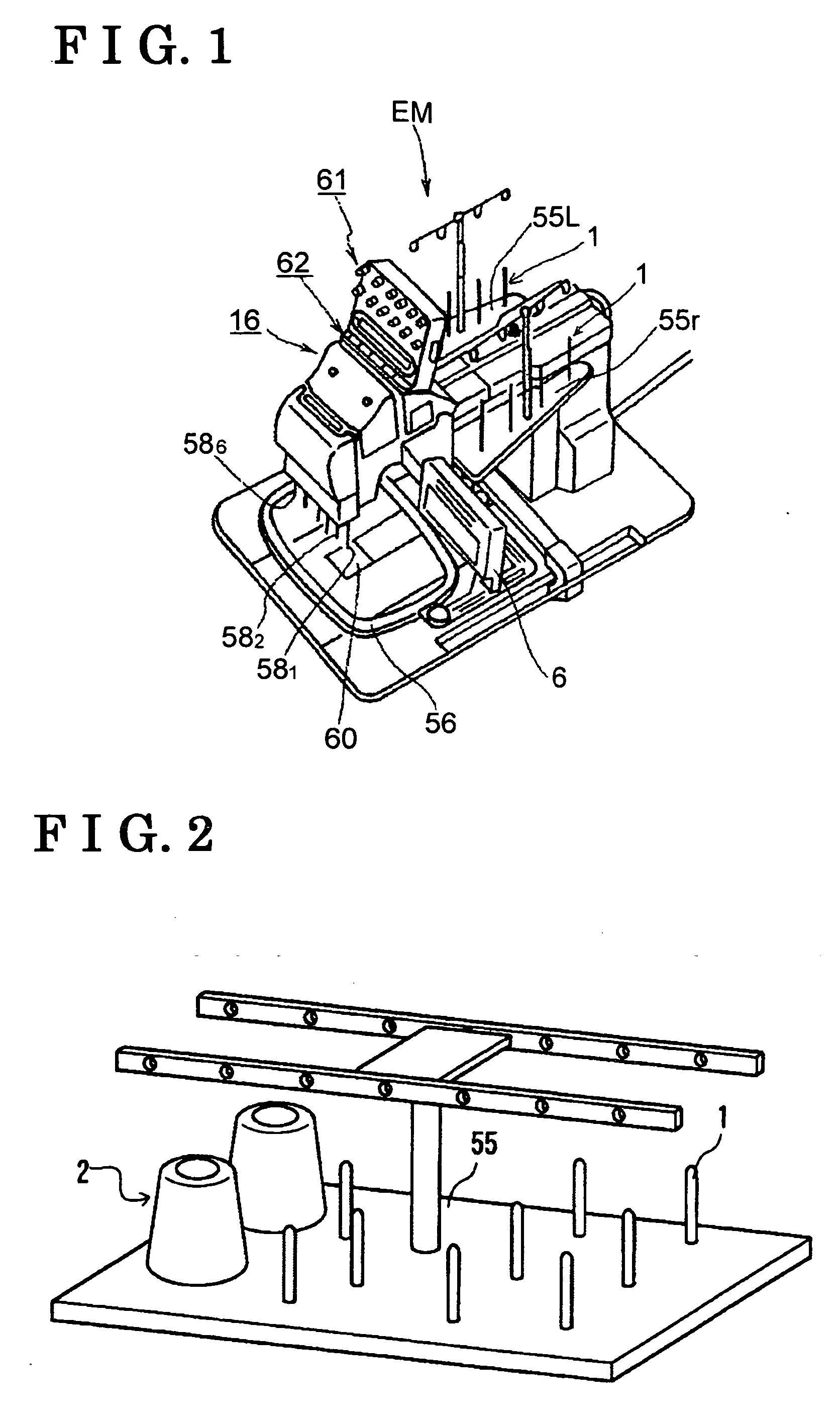
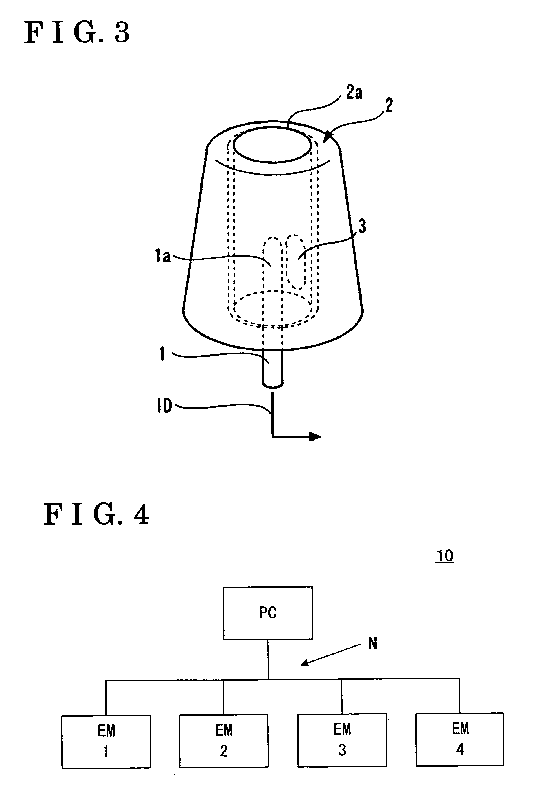
[0016] An embodiment of the present invention will be explained. In the embodiment of the present invention, when a thread reel to which a wireless tag is attached in advance is installed to a thread reel stand bar of one embroidery machine or a plurality of embroidery machines equipped with multiple needles and of automatic thread-changing type having a receiving device for receiving signals from the wireless tag, the embroidery machine reads an identification (ID) of the thread wound around the thread reel through the receiving device. Then, the embroidery machine searches a database of thread ID and associated thread information stored in a server PC provided in a network for finding the thread ID and obtaining the associated thread information from the database.
[0017] The thread information to be obtained includes a manufacturer of the thread, a thread color (indicated by number or RGB code), material of thread (rayon, polyester or the like), or a thread thickness. In the syste...
PUM
 Abstract
Description
Claims
Application Information