Driving device and optical instrument

Inactive Publication Date: 2006-03-23
FUJIFILM HLDG CORP +2
View PDF12 Cites 18 Cited by
  • Summary
  • Abstract
  • Description
  • Claims
  • Application Information

AI Technical Summary

Benefits of technology

[0010] In view of the foregoing problems, an object of the present invention is to provide a driving device and optical instrument in which a piezoelectric element is used to apply force to a device to be driven, and with which a stroke of the driven device can be large even in a simple structure.

Problems solved by technology

There are problems in the above-indicated prior documents.

Method used


Image

  • Driving device and optical instrument
  • Driving device and optical instrument
  • Driving device and optical instrument

Examples


Embodiment Construction

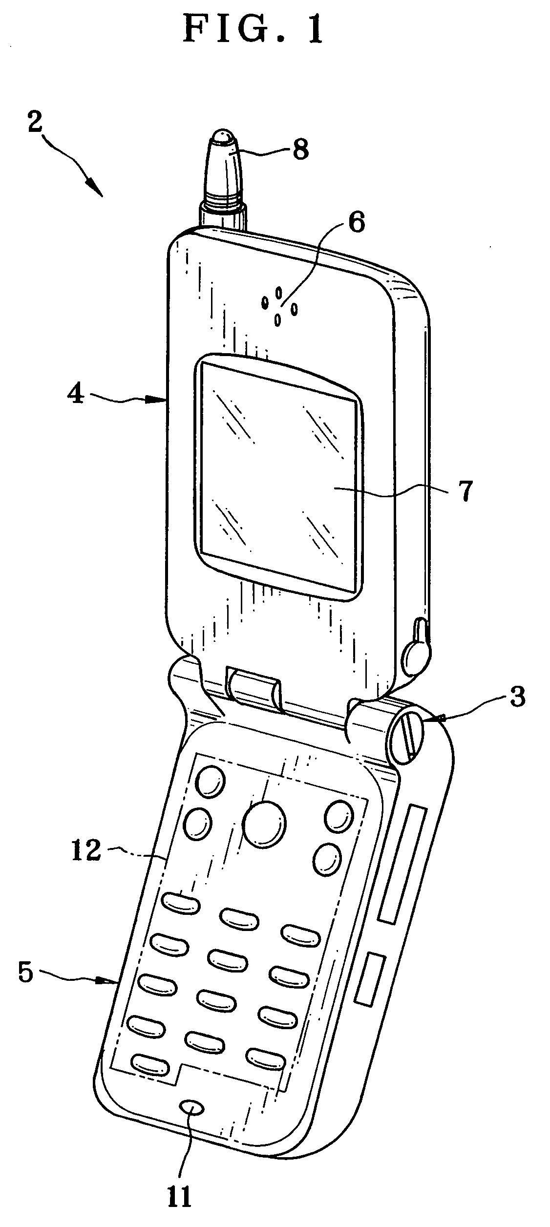
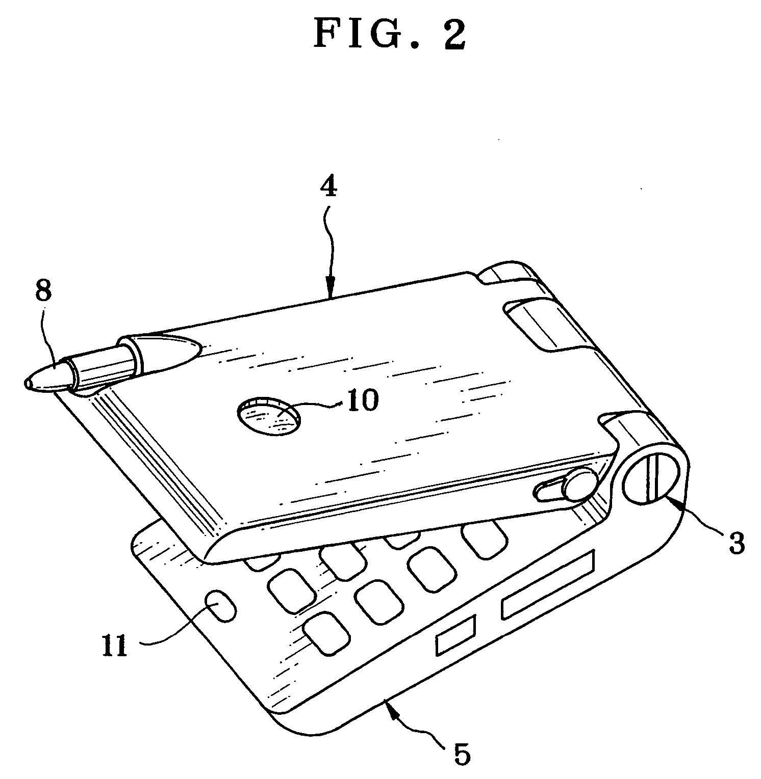
[0057] In FIGS. 1 and 2, a camera-built-in cellular telephone handset 2 as image pickup device is illustrated. The cellular telephone handset 2 includes a reception unit 4 and a transmission unit 5. A hinge 3 in the cellular telephone handset 2 interconnects the reception unit 4 and the transmission unit 5, and keeps the cellular telephone handset 2 foldable for portability.

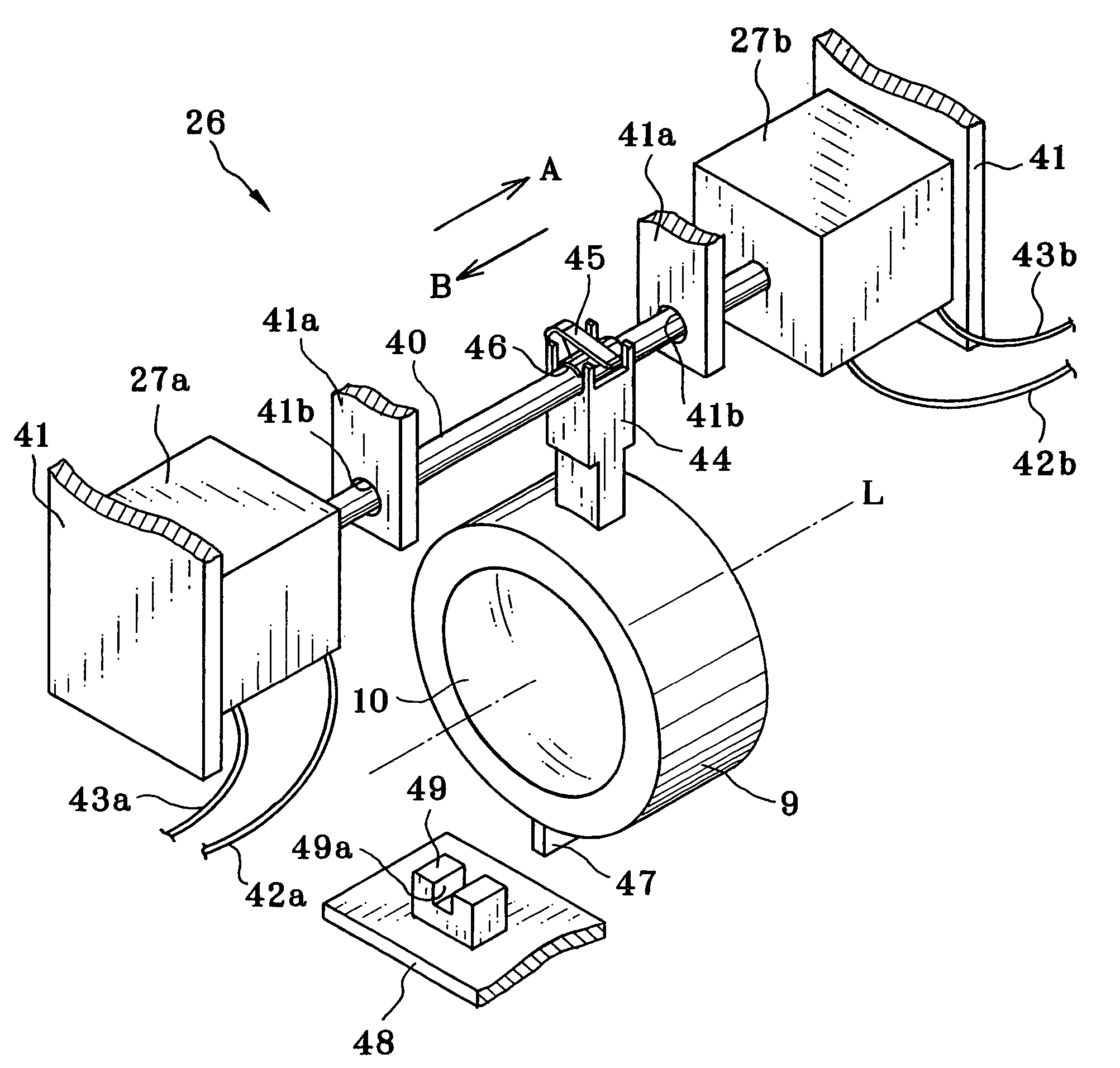
[0058] A front of the reception unit 4 is provided with a speaker 6 and an LCD (liquid crystal display) panel 7. The speaker 6 outputs sounds, voices and the like. The LCD panel 7 displays visible information, such as menu patterns and a retrieved image photographed by a built-in camera. An antenna 8 is disposed on the rear of the reception unit 4, and transmits and receives radio waves for communication. An image pickup lens 10 appears in the front. A lens barrel 9 as a movable structure supports the image pickup lens 10 inside. See FIG. 4. A front of the transmission unit 5 is provided with a transmission micr...


PUM


Abstract

A piezoelectric actuator having a frame portion includes a drive shaft for frictional engagement with an engageable barrel arm of a lens unit. First and second piezoelectric elements are supported on the frame portion, and provided with first and second ends of respectively the drive shaft. A drive pulse generator supplies the piezoelectric elements with a drive signal to expand or contract the piezoelectric elements, and moves the engageable barrel arm in an axial direction by an alternately repeating sequence of shifting the drive shaft at low and high speeds in the axial direction. In the shifting at the high speed, the piezoelectric elements shift the drive shaft in a backward direction quickly, to move the drive shaft in the backward direction relative to the engageable barrel arm being stationary with inertial force.

Description

BACKGROUND OF THE INVENTION [0001] 1. Field of the Invention [0002] The present invention relates to a driving device and optical instrument. More particularly, the present invention relates to a driving device and optical instrument in which a piezoelectric element is used to apply force to a device to be driven. [0003] 2. Description Related to the Prior Art [0004] An optical instrument such as a camera includes an actuator as a driving device, and a mechanical element for being driven by the actuator. For example, U.S. Pat. No. 5,225,941 (corresponding to JP-A 4-069070) and U.S. Pat. No. 5,589,723 (corresponding to JP-A 7-274543) disclose a use of a piezoelectric actuator in a camera as an electromechanical converting element or transducer. [0005] In FIG. 21, a piezoelectric actuator of the prior art for use with a lens is illustrated. A lens barrel 100 as an element to be driven includes a projection 101 and holes 101a and 101b. The projection 101 projects from the periphery of ...

Claims


Application Information

Patent Timeline
Patent Type & Authority Applications(United States)
IPC IPC(8): H01L41/09
CPCH02N2/067H02N2/025
Inventor ITO, YOSHIHIRONAKA, YOJISENBA, TAKEHIKOONOZUKA, HARUONOGUCHI, YUKIOMANABE, MITSUO
Owner FUJIFILM HLDG CORP
Why Eureka
Try Eureka