Self-latching device for fastening a hinged closure member

a self-latching device and closure member technology, which is applied in mechanical control devices, keyhole guards, restricting/preventing/returning movement of parts, etc., can solve the problem that the gate cannot be simply closed, and achieve the effect of reliable latching and large sagging of the closure member

Active Publication Date: 2009-01-06
TALPE JOSEPH
View PDF10 Cites 10 Cited by
  • Summary
  • Abstract
  • Description
  • Claims
  • Application Information

AI Technical Summary

Benefits of technology

[0007]An object of the present invention is now to provide a new self-latching device of the above-defined type which enables to latch the closure member at a certain height on this closure member and which can ea

Problems solved by technology

A drawback of this know fastening device is that the gate cannot simply be closed without having to oper

Method used


Image

  • Self-latching device for fastening a hinged closure member
  • Self-latching device for fastening a hinged closure member
  • Self-latching device for fastening a hinged closure member

Examples


Embodiment Construction

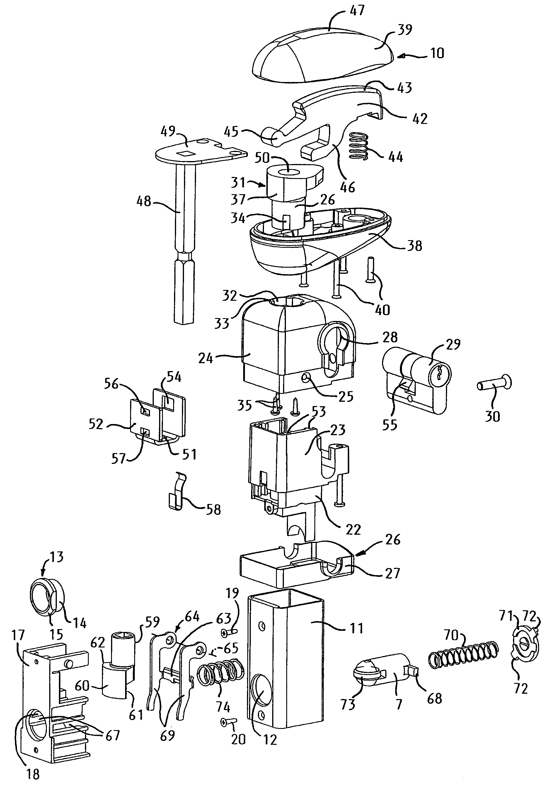
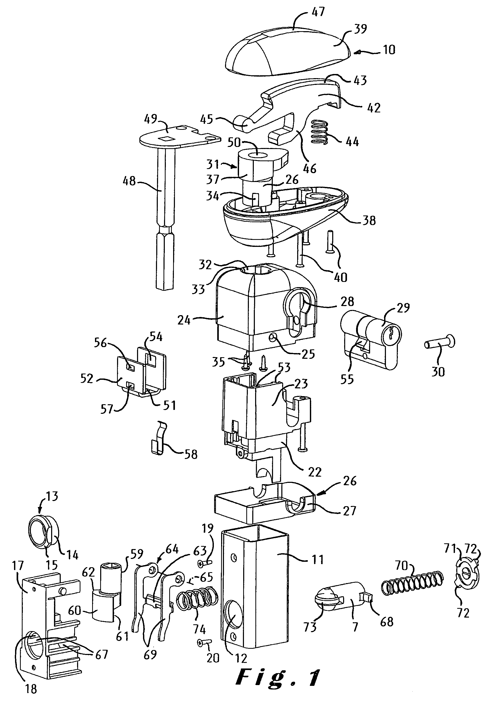
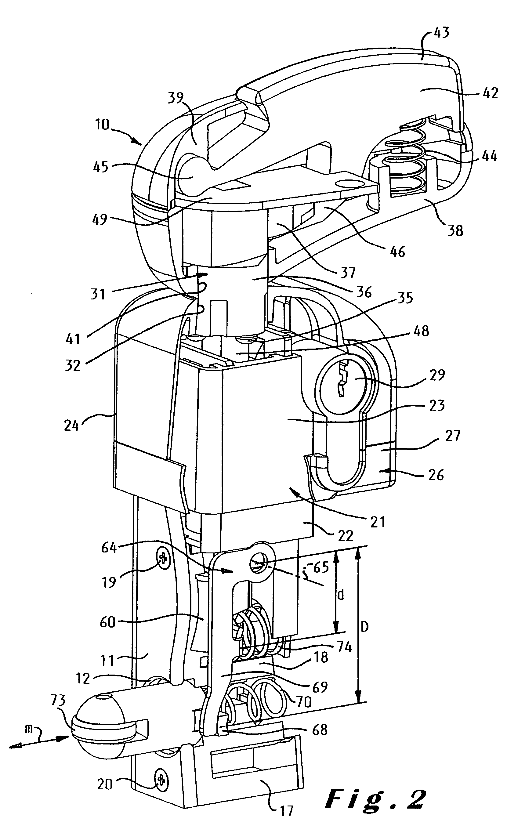
[0037]The self-latching device illustrated in the drawings is intended to be mounted in an upright position onto a hinged closure member 2, in particular a gate or a door. The device is more particularly intended to be mounted in a vertical tubular member 1 which is either an integral part of the gate 2 (see FIGS. 8 to 10) or which is fixed to the gate 2 (see FIG. 12). The tubular member 1 can be fixed for example by means of self drilling screws to the gate 2 so that no holes have to be drilled in the gate. The latching device comprises a latch bolt 7 which co-operates with a striker element 3 on an opposite post 5. This striker element 3 can also be fixed by means of self drilling screws 4 to the post 5 (see FIGS. 11 and 12). The post may be a fixed post, in particular a fence post 5, but it may also be another closure member such as the other gate member of a double gate.

[0038]The striker element 3 comprises an elongate cavity 6 arranged to receive the latch bolt 7, an inclined s...


PUM


Abstract

The self-latching device comprises a frame (11, 17, 21, 24, 31) arranged to be mounted on the hinged closure member, in particular on a gate, a latch bolt (7) movably mounted on the frame in a horizontal direction between a latching position and a retracted position, a latch bolt spring (70) arranged to bias the latch bolt (7) into the latching position, and operator means (10) mounted on top of the frame so as to be operable from both sides of the closure member (2) and connected by means of a latch bolt operating mechanism to the latch bolt (7) for moving it from the latching to the retracted position. The self-latching device is especially suited for being mounted in a vertical tubular member of or fixed to a safety gate around an area which is dangerous for children, in particular around a swimming pool area.

Description

BACKGROUND OF THE INVENTION[0001]The present invention relates to a self-latching device for fastening a hinged closure member, in particular a door or a gate, which device comprises a frame arranged to be mounted on the hinged closure member, a latch bolt mounted on said frame so as to be movable in a predetermined direction between a latching position and a retracted position, the latch bolt being a self-latching bolt arranged to be moved towards its retracted position by contact with a striker element when closing the closure member, a latch bolt spring arranged to bias the latch bolt into the latching position, and operator means mounted on top of the frame so as to be operable from both sides of the closure member and connected by means of a latch bolt operating mechanism to the latch bolt for moving it from the latching to the retracted position.[0002]The self-latching device can be mounted on various types of doors, gates, etc. However, the latching device according to the pr...

Claims


Application Information

Patent Timeline
IPC IPC(8): B60R25/02
CPCE05B65/0007E05B65/0014Y10T70/577Y10T292/097
Inventor TALPE, JOSEPH
Owner TALPE JOSEPH
Why Eureka
Try Eureka