
Mechanical locking of floor panels with vertical folding

A technology of vertical folding and floor paneling, which can be applied to floors, buildings, building structures, etc., and can solve problems such as difficulty in paneling

Inactive Publication Date: 2013-09-11
VÄLINGE INNOVATION AB
View PDF2 Cites 0 Cited by
  • Summary
  • Abstract
  • Description
  • Claims
  • Application Information

AI Technical Summary

Problems solved by technology

This strong tongue is very important in many applications where a high quality vertical connection is required and it is very difficult to install panels with such a flexible tongue by known installation methods

Method used


Image

  • Mechanical locking of floor panels with vertical folding
  • Mechanical locking of floor panels with vertical folding
  • Mechanical locking of floor panels with vertical folding

Examples


Embodiment Construction

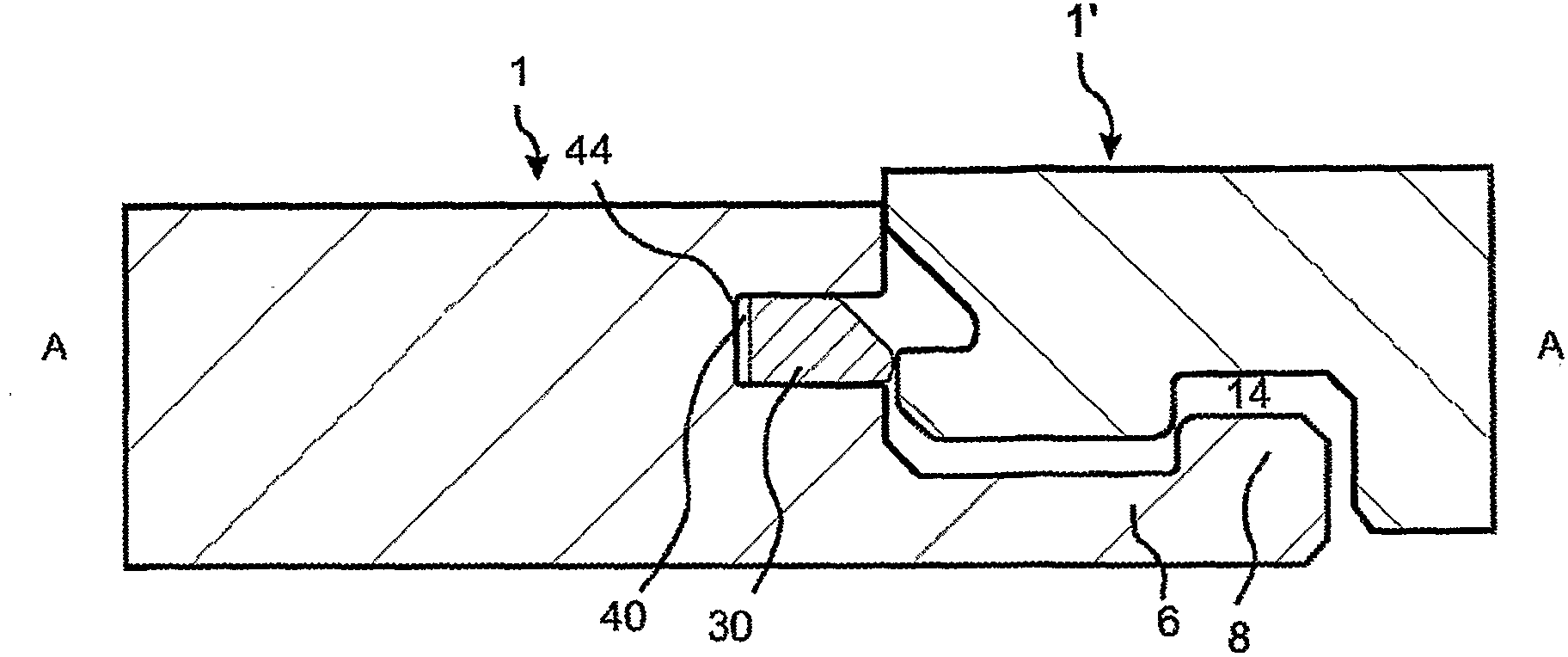
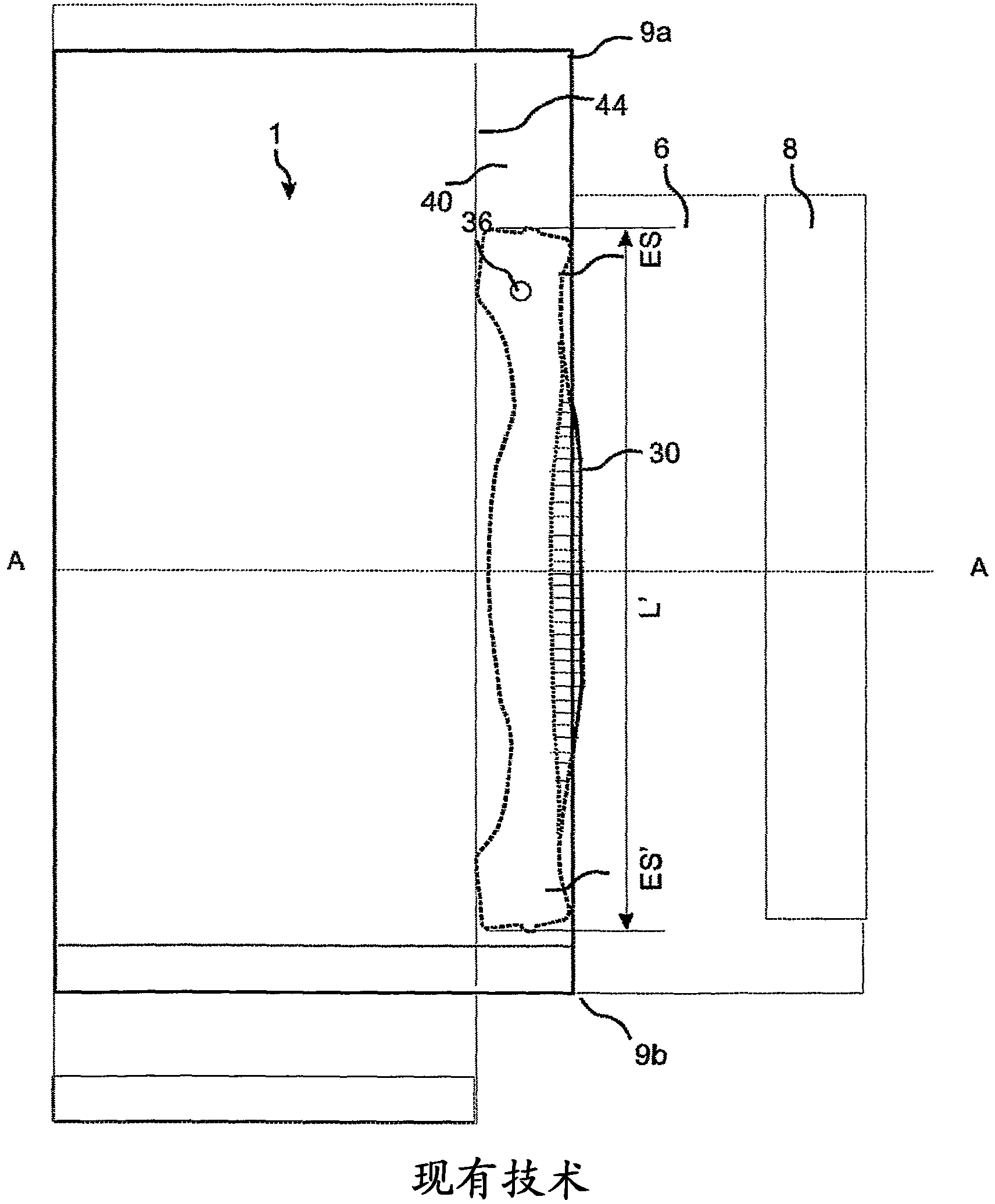
[0091] 1-6 and the related description below illustrate the disclosed embodiments and serve to explain the general principles of the invention and to illustrate examples of embodiments that can be used in the invention. The illustrated embodiments are examples only. It should be emphasized that all types of flexible and one-piece tongues that can be used in a locking system capable of vertical folding and / or vertical locking can be used and that applicable parts of this description form part of the invention.

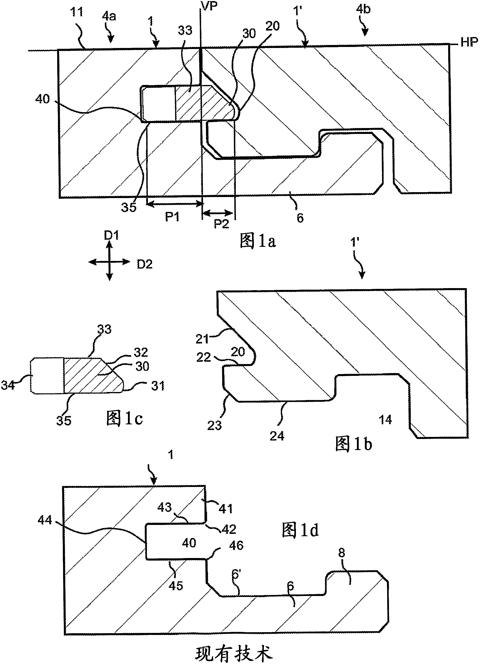
[0092] refer to Figures 1a-1d A prior art floor panel 1, 1' with a mechanical locking system and a displaceable tongue is described.

[0093] Figure 1a A cross-section of a joint between a short edge joint edge 4a of a panel 1 and an opposite short edge joint edge 4b ​​of a second panel 1' is schematically shown.

[0094] The front faces of the panels are positioned substantially in a common horizontal plane HP and the upper parts 21 , 41 of the joint edges 4a...


PUM

PropertyMeasurementUnit
frictionaaaaaaaaaa
friction angleaaaaaaaaaa
contact angleaaaaaaaaaa

Abstract

Floor panels (1, 1', 1' ' ) are shown, which are provided with a mechanical locking system on long and short edges (5a, 5b, 4a, 4b) allowing installation with vertical folding and where the long edge(5a, 5b) locking system prevents separation of the short edges (4a, 4b) during the folding action.

Description

[0001] This application is a divisional application of the patent application with the application number 200780049875.9. The filing date of the original application is October 25, 2007, and the name is "mechanical locking of floor panels realized by vertical folding". technical field [0002] The present invention mainly relates to the field of floor panels with a mechanical locking system with a flexible displaceable tongue that facilitates installation. The present invention provides a new and improved locking system and method of installation. Background technique [0003] In particular but not limitatively, the present invention relates to a mechanical locking system for rectangular floor panels having long and short edges. It should be emphasized that the long and short edges are only used to simplify the description. The floor panels can also be square. In general, however, the invention is equally applicable to architectural panels. More particularly, the present ...

Claims


Application Information

Patent Timeline
Patent Type & Authority Applications(China)
IPC IPC(8): E04F15/02
CPCE04F15/02E04F15/04E04F2201/0138E04F2201/0153E04F2201/0176E04F2201/0523E04F2201/0535E04F2201/0547E04F2201/0576E04F2201/0588E04F15/02038E04F2201/02E04F2201/05
Inventor D·佩尔万
Owner VÄLINGE INNOVATION AB
Learn More