Flexible Transmission Device for Tool Extensions and the Like

a transmission device and extension technology, applied in the direction of couplings, manufacturing tools, mechanical apparatus, etc., can solve the problems of reducing or voiding the torque transmission functionality between the mating couplers, limiting the attainable amount of overall flexibility between the drive and the socket, and the conventional tool design requires a notable amount of axial space. , to achieve the effect of smooth contouring

Inactive Publication Date: 2014-03-13
DAUVIN JAE E +1
View PDF12 Cites 62 Cited by
  • Summary
  • Abstract
  • Description
  • Claims
  • Application Information

AI Technical Summary

Benefits of technology

[0051]The collar of each intermediate link may comprise a second annular end face opposite the flat annular end face, the second annular end face having a smooth transition from a maximum axial length of the collar at the first plane to a minimum axial length of the collar at the second plane.
[0

Problems solved by technology

A known problem in the use of torque transmitting tools such as socket wrenches, impact guns, screwdrivers, etc. is that conventional tool designs require a notable amount of axial space by which the tool can approach the fastener (nut, bolt, fastener) in a straight on manner along the fastener's rotational axis.
However, one potential problem with the design is that repeated use in higher torque applications, for example use of an impact gun compared to lower torque hand to

Method used


Image

  • Flexible Transmission Device for Tool Extensions and the Like
  • Flexible Transmission Device for Tool Extensions and the Like
  • Flexible Transmission Device for Tool Extensions and the Like

Examples


first embodiment

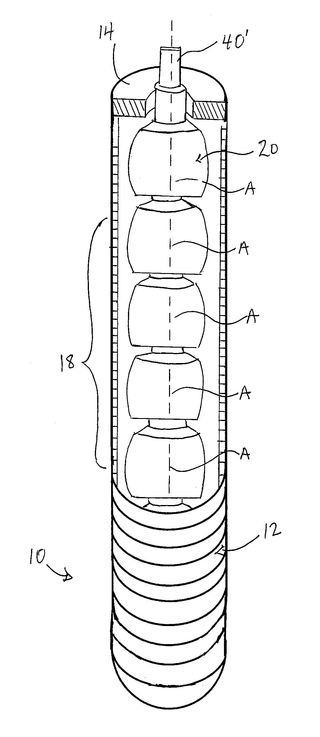
[0117]FIG. 1 shows a flexible tool extension 10 according to the present invention which can be coupled between the female rectangular drive opening of a socket and the male rectangular drive stud of a socket wrench or impact gun in order to allow rotational drive of the socket by the wrench or impact gun without direct axial alignment therebetween.

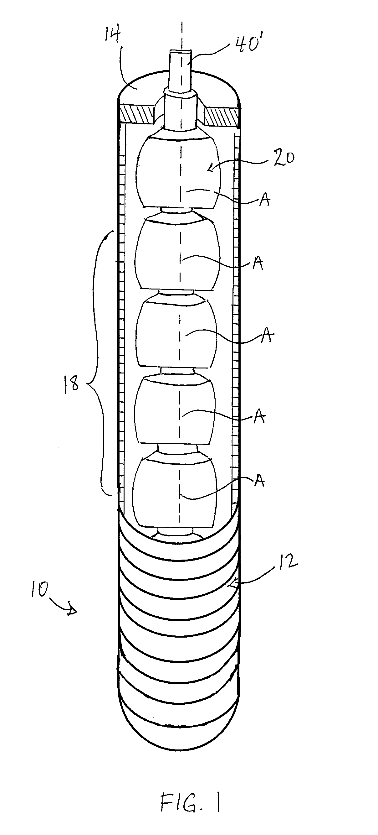
[0118]The extension features a flexible outer jacket 12 provided in the form of a length of conventional flexible metallic conduit or tubing having an annular closure 14 (only one of which is visible in the drawings) at its two ends to define a housing in which a number of internal components are maintained. These internal components include a drive end adapter 16 (not visible in FIG. 1), a plurality of intermediate couplers 18, and a working end adapter 20, all connected together in series to run along the interior of the flexible jacket 12 with the two adapters 16, 20 respectively lying just inside the two closed ends of the jacket, and...

second embodiment

[0147]This style of pivotal connection between adjacent casing members means that the mating male-female members of the connected pair of casing members are in-plane with one another, as best shown in FIG. 12B, unlike the second embodiment where the pin-carrying lug and corresponding hole-equipped flat of the connected casing members are in adjacent, but separate, parallel planes, and are interconnected laterally (i.e. radially, relative to the bore axes of the casing links) by the pin.

third embodiment

[0148]This in-plane mating of male and female elements 162, 168 on diametrically opposing sides of the casing links to form the pivotal connection between casing members in the third embodiment is used to define a pair of stiffener-receiving passages that run along these opposing sides of the casing 112 from one end link thereof to the other. As shown in the cross-sectional views of FIGS. 12B and 12C, a closed channel 200 extends axially through each ear and slot equipped side of each intermediate link 150 so as to reach from the inner end of the recess 168 furthest from the end of the collar into which the recess extends, onward to the distal end of the ear 162 of the same link furthest from the end of the collar from which the ear projects. In a plane perpendicular to the pivot axis of the pivotal connection formed by the mating of the ear 162 in the respective recess of the next link, the channel 200 is tapered so as to grow wider from the end 202 of the channel that opens into t...


PUM


Abstract

Flexible transmission devices, for example for use a tool extensions for effecting rotation of fasteners that are difficult or impossible to access straight on using the normal output of a tool. A series of internal couplers are connected together end-to-end by constrained ball and socket joints that allow tilting between the axes of the couplers while constraining relative rotation of the couplers about said axes. The internal couplers form a flexible shaft inside an outer casing formed by a series of collar-shaped links joined in adjacent pairs by a single-axis pivot connection, each positioned to coincide with a respective one of the ball and socket joints.

Description

CROSS REFERENCE TO RELATED APPLICATIONS[0001]This application claims benefit under 35 U.S.C. 119(a) of Canadian Patent Application Serial No. 2,789,488, filed Sep. 13, 2012, the entirety of which is incorporated herein by reference.FIELD OF THE INVENTION[0002]The present invention relates generally to flexible transmission devices, useful for example as flexible extensions for torque transmitting tools, and more particularly to a device featuring internal couplings fitted axially together in series through male and female ends forming constrained ball and socket joints that allow relative pivoting between the axes of the couplings while employing radial projections and matching slots to transmit torque from one coupling to the next, and an external casing formed by a series of collar-shaped links with single-axis pivotal connection between adjacent links.BACKGROUND OF THE INVENTION[0003]A known problem in the use of torque transmitting tools such as socket wrenches, impact guns, scr...

Claims


Application Information

Patent Timeline
IPC IPC(8): B25B23/00
CPCB25B23/0021B25B23/0028F16D3/2057F16C1/04F16C1/06F16C2226/78
Inventor DAUVIN, JAE E.DAUVIN, GEORGE A.
Owner DAUVIN JAE E
Why Eureka
Try Eureka