

Medical connector
a technology of medical connectors and connectors, applied in the direction of tube connectors, catheters, other medical devices, etc., to achieve the effect of preventing accidental or undesirable separation
- Summary
- Abstract
- Description
- Claims
- Application Information
AI Technical Summary
Benefits of technology
Problems solved by technology
Method used
Image

Examples
Embodiment Construction
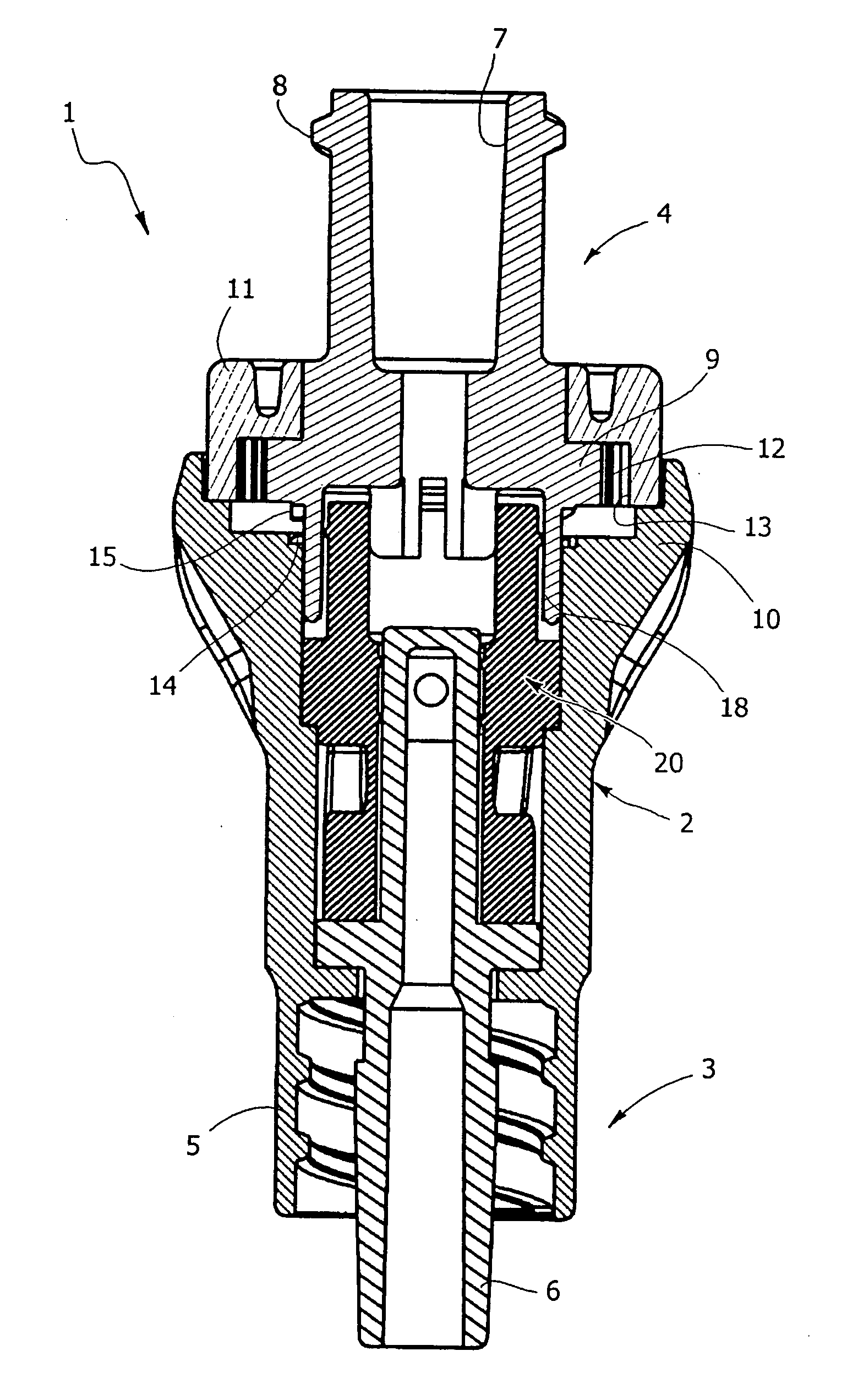
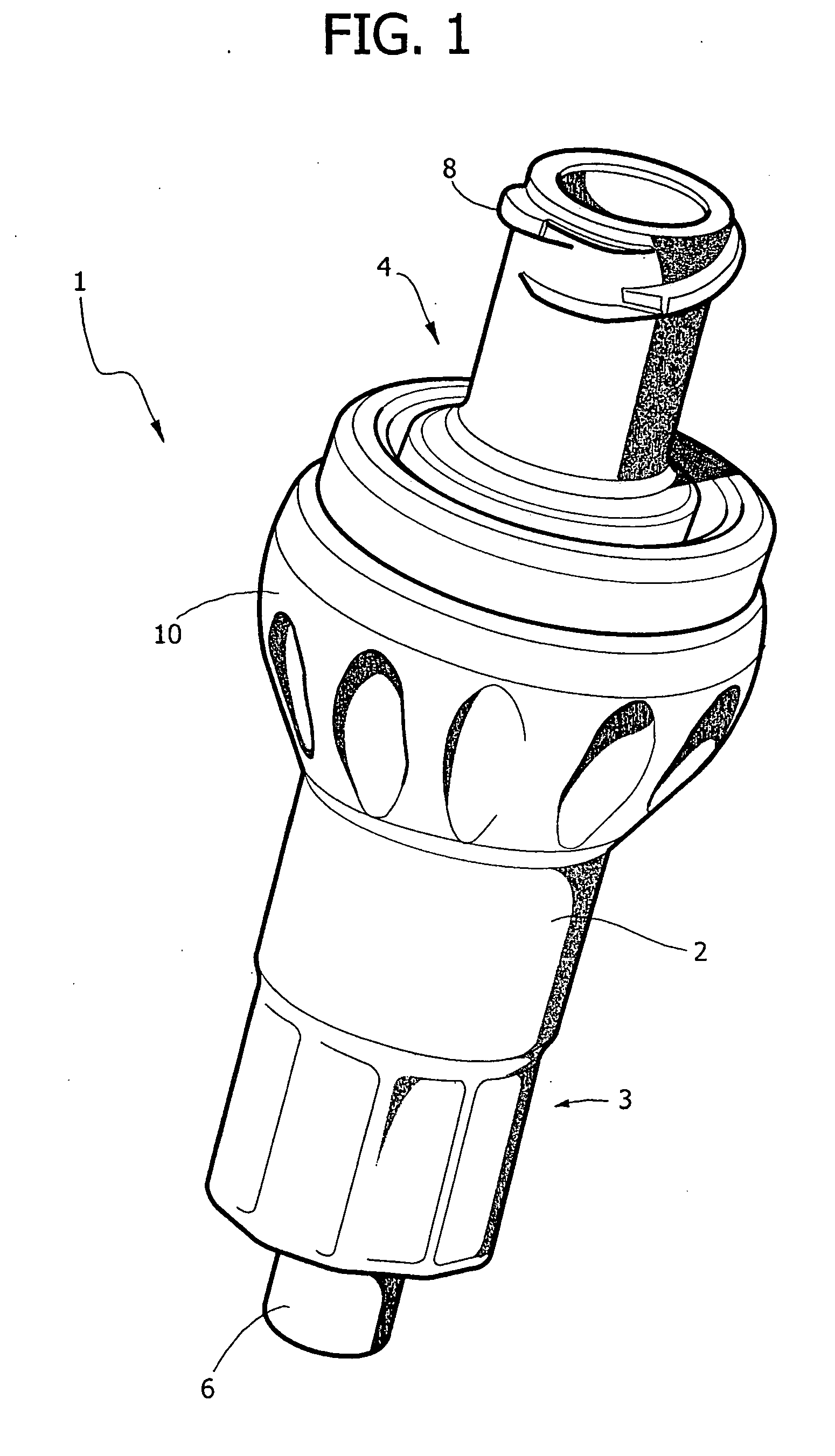
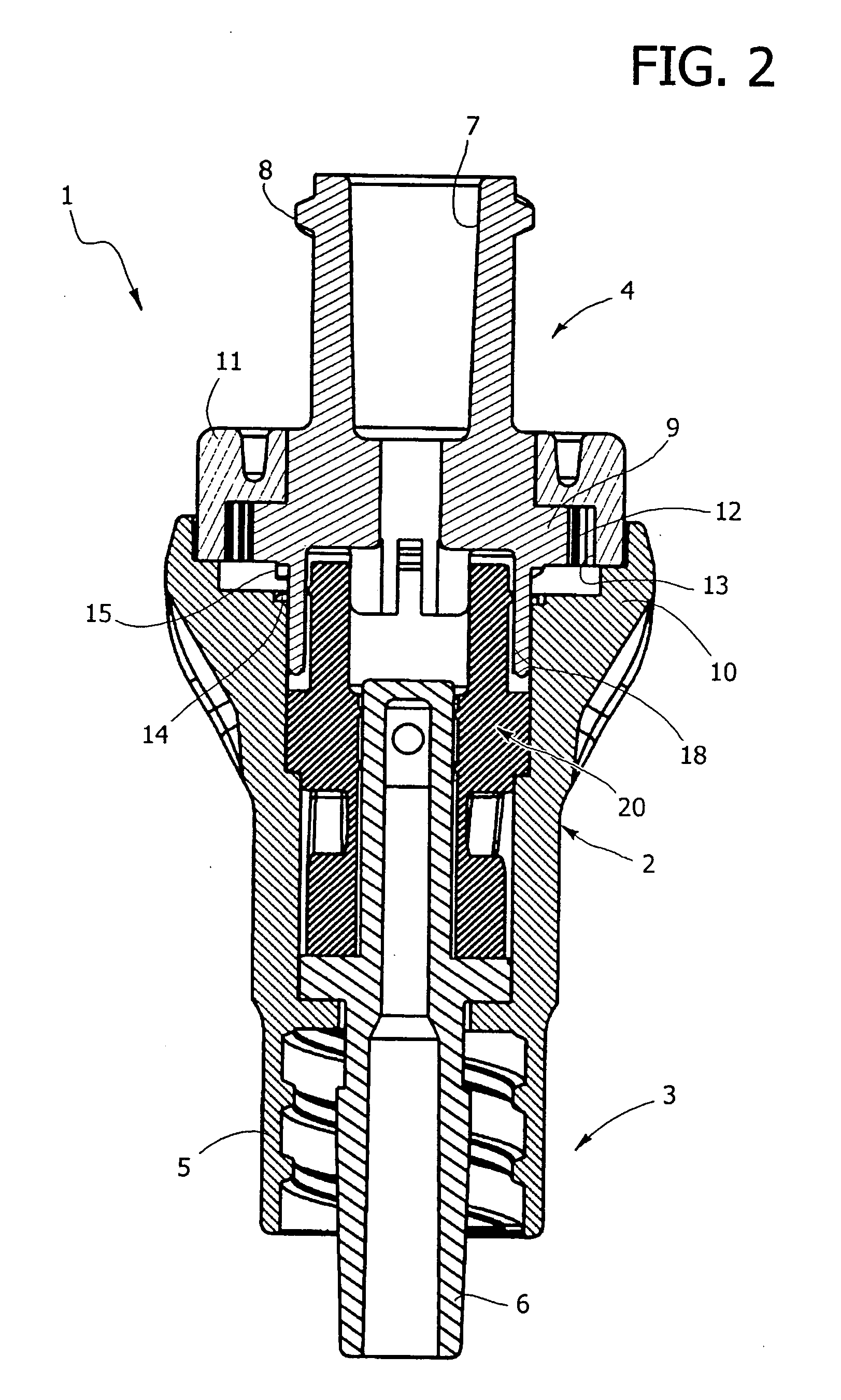
[0013] With reference to the drawings, number 1 designates as a whole a medical connector according to the invention, basically comprising a tubular body 2 provided, coaxially with respect to its ends, with an inlet fitting 3 and an outlet fitting 4 that is connectable to a pipe of a medical line, for example an infusion line. The above-described components of the medical connector 1 are all made of moulded plastic material.
[0014] With reference now in greater detail to FIG. 2, in the case of the example illustrated the inlet fitting 3 is of the male luer-lock type, with an external hollow part 5, internally threaded and formed integrally with the body 2, and an internal tubular part 6 that can slide axially with respect to the external part 5. It should be noted that the illustrated conformation of the male luer-lock fitting 3 is not significant for the purposes of the present invention, and indeed forms a subject of a parallel Italian patent application filed on the same date in ...
PUM
 Abstract
Description
Claims
Application Information