
High bandwidth large stroke spin-stand

Inactive Publication Date: 2006-12-26
SEAGATE TECH LLC
View PDF22 Cites 10 Cited by
  • Summary
  • Abstract
  • Description
  • Claims
  • Application Information

AI Technical Summary

Benefits of technology

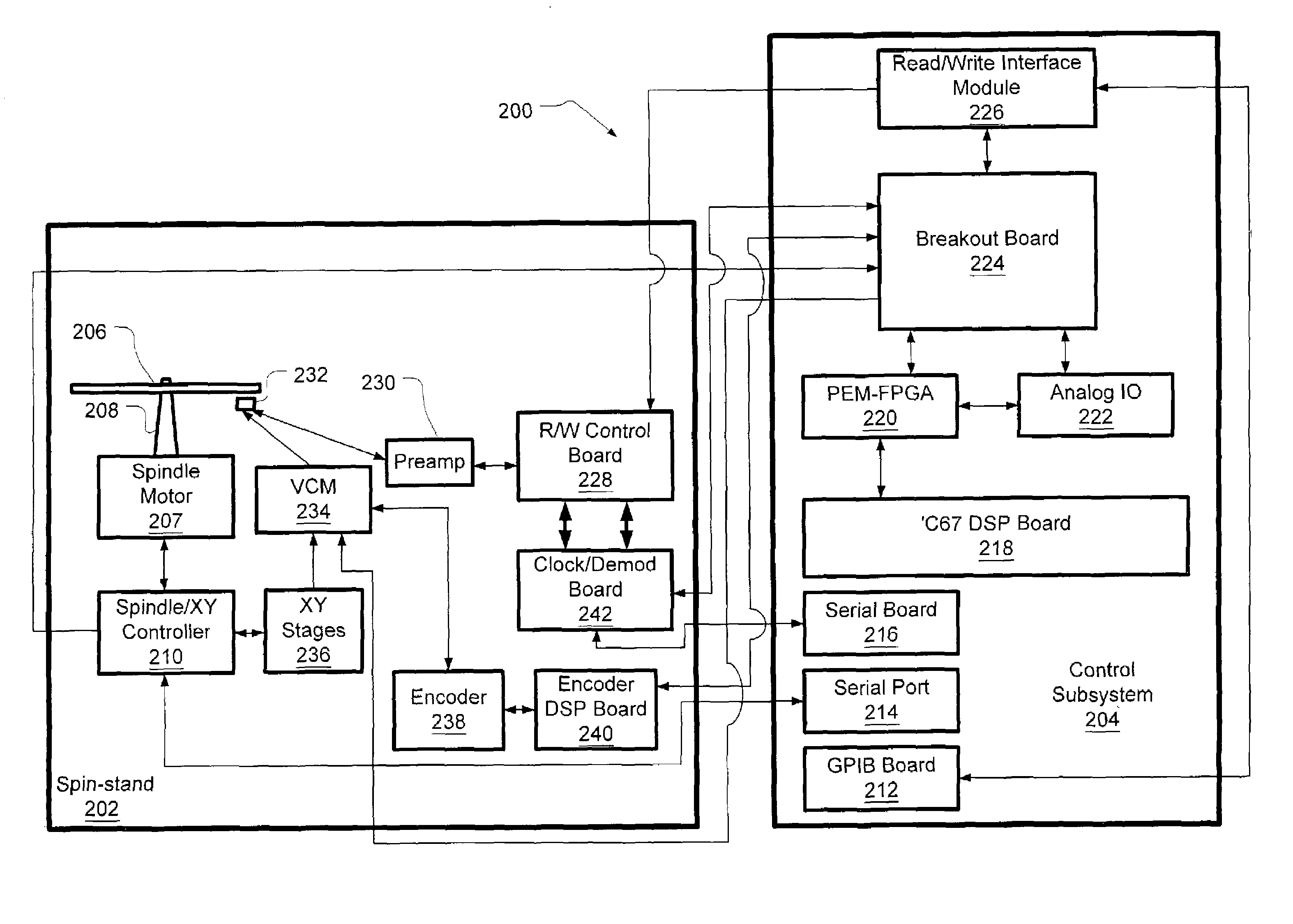
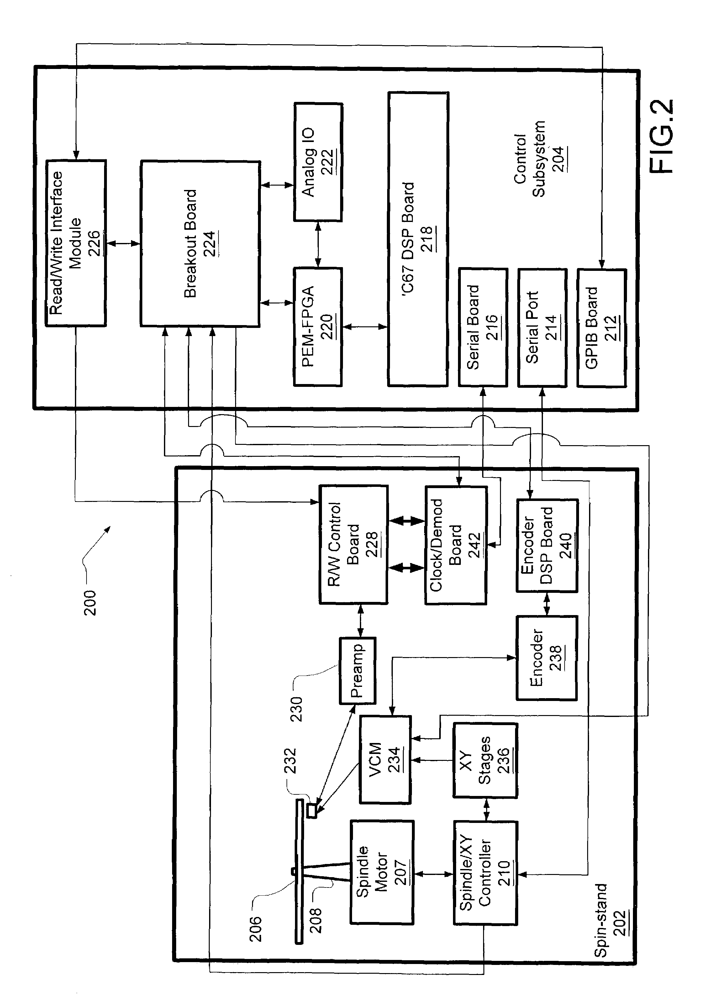
[0008]Against this backdrop the present invention has been developed. A high bandwidth, large stroke spin-stand for testing components of a disc drive includes a coarse positioning stage and a rotary micropositioning stage. The spin-stand is capable of positioning a transducer head relative to the data storage disc based on one or both of: (1) an angular position of a rotary actuator arm in the rotary micropositioning stage; and (2) servo data read from the data storage disc. The

Problems solved by technology

Therefore, positioning a transducer head precisely within a track becomes increasingly important and difficult.
In fact, it is axiomatic that the precision of test equipment must exceed that of the improved data storage disc drives that it tests.
However, even the existing two stage motion platforms cannot provide the needed precision and movement for higher density disc drives.
A positioning staging having this capability is referred to herein as having “high bandwidth.” However, piezoelectric actuators used in existing spin stands cannot compensate for such high frequency variations observed in higher density data storage disc drives.
Such operation is referred to as “track following.” Existing motion platforms may be adequate for following ideally (or almost ideally) circular recorded tracks, but prewritten tracks on higher density data storage discs will typically be too eccentric with respect to the spindle of the spin-stand (e.g., due to tolerances in the spindle clamp).
A positioning stage having this capability is referred to herein as having a “large stroke.” However, piezoelectric actuators presently used in existing spin stands cannot support such large amplitude irregularities observed in higher density data storage disc drives.

Method used


Image

  • High bandwidth large stroke spin-stand
  • High bandwidth large stroke spin-stand
  • High bandwidth large stroke spin-stand

Examples


Embodiment Construction

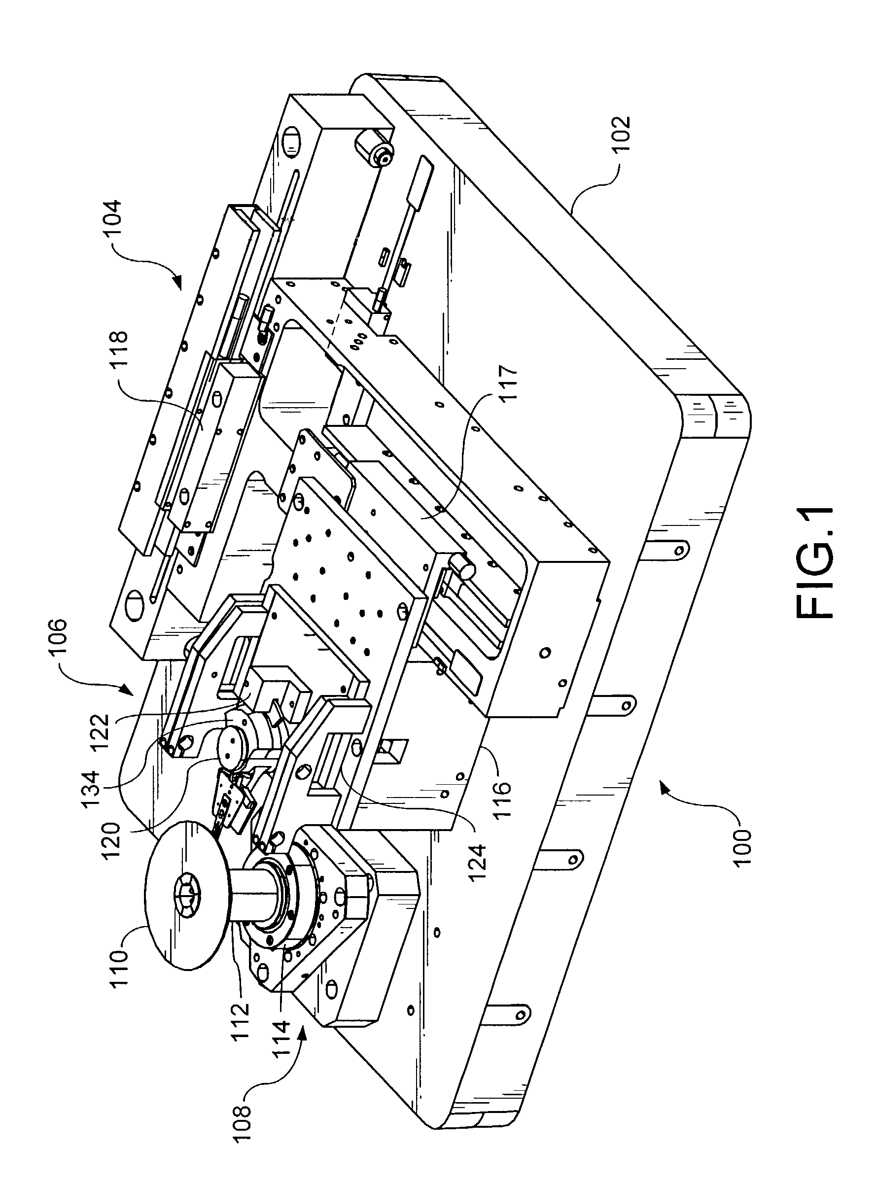
[0017]FIG. 1 is a perspective view of a high bandwidth large stroke spin-stand 100 in an embodiment of the present invention. The base 102 may be constructed of any heavy and sturdy material, such as cast iron or granite, to provide stability in the spin-stand. In one embodiment of the present invention, a stable table or cabinet section (not shown) is positioned below the base 102 to raise the operational portion of the spin-stand to a convenient working height.

[0018]The spin-stand 100 includes a coarse positioning stage 104, a rotary micropositioning stage 106, and a spindle subsystem 108. During a test, a data storage disc 110 is loaded on the spindle 112 of the spindle subsystem 108. The data storage disc 110 may be unwritten or may have prewritten tracks already recorded on its recording surface. In one embodiment, the spindle 112 extends vertically upward from an air bearing 114, although other orientations are also contemplated within the scope of the present invention, inclu...


PUM


Abstract

A high bandwidth, large stroke spin-stand for testing components of a disc drive includes a coarse positioning stage and a rotary micropositioning stage. The spin-stand is capable of positioning a transducer head relative to the data storage disc based on one or both of: (1) an angular position of a rotary actuator arm in the rotary micropositioning stage; and (2) servo data read from the data storage disc. The angular position of the rotary actuator arm is detected by an encoder. In one embodiment, position adjustments are based on the detected angular position. In another embodiment, position adjustments are based on servo data read from the data storage disc, but are also conditional on angular position being consistent with the servo data. In yet another embodiment, both angular position and servo data from a track are linearized to generate PES adjustment parameters that are recorded on the data storage disc to redefine the track as more circular or to linearize the PES.

Description

RELATED APPLICATIONS[0001]This application claims priority of U.S. provisional application Ser. No. 60 / 302,596, filed Jul. 2, 2001 and entitled “High Bandwidth Large Stroke Spin-stand for Component Testing”.FIELD OF THE INVENTION[0002]This application relates generally to disc drive testing and more particularly to a spin-stand for testing disc drive components.BACKGROUND OF THE INVENTION[0003]Disc drive storage capacities are continuing to increase dramatically, resulting in part from rapid advances in on-disc coding schemes and magnetic sensitivities of read / write head components. Data (including servo data) is magnetically stored on concentric tracks patterned on the disc. The increase in track density on the disc relates to a corresponding decrease in the width of the read and write heads (e.g., transducer heads). As areal densities increase, previously negligible position error effects become more prominent. Therefore, positioning a transducer head precisely within a track beco...

Claims


Application Information

Patent Timeline
IPC IPC(8): G11B5/596G11B5/55
CPCG11B5/5552G11B5/596
Inventor SUBRAHAMANYAN, PRADEEP K.KORKOWSKI, PATRICK J.FARAHAT, WALEED A.EHRET, STEVEN CSEVERSON, GREGG J.RASMUSSEN, THOMAS SVAN DER SCHANS, ALBERTSACKS, ALEXEI H.MCGLENNEN, JAMES H.
Owner SEAGATE TECH LLC
Learn More