Transverse electrodisplacive actuator array

a technology of electrodisplacive actuators and actuator arrays, applied in piezoelectric/electrostrictive/magnetostrictive devices, mirrors, instruments, etc., can solve the problems of complex mutilayer actuator configuration, very sensitive to electrostrain induced stress failure, and unable to meet the requirements of electrical induced failure,

Active Publication Date: 2005-06-16
NORTHROP GRUMMAN SYST CORP
View PDF19 Cites 11 Cited by
  • Summary
  • Abstract
  • Description
  • Claims
  • Application Information

AI Technical Summary

Benefits of technology

[0012] It is a further object of this invention to provide such an improved transverse electrodisplacive actuator array which is scalable by assembling a number of such arrays.
[0013] The invention results from the realization that an improved electrodisplacive actuator array for controlling the optical phasing of a reflective surface having reduced interfacial stress between the actuator element material and the electrodes and having a stroke dependent on the length of the actuator element not the number of laminates stacked can be achieved by utilizing the transverse instead of the longitudinal strain to move the reflective surface and that this can be effected by orienting the electrodes of each actuator element longitudinally instead of laterally so that the force is applied in the d31 axis with the laminations of electrodes and actuator element ceramic instead of in the d33 axis through the laminations thereby reducing the stress on the interfaces and

Problems solved by technology

The net result is a complex mutilayer actuator configuration which is very sensitive to electrostrain induced stress failure.
Flaws in the ceramic structure such as voids and impurities also create localized regions of very large stresses.
It is not surprising that nearly all electrically induced failure occurs at this interface, not in the ceramic.
Electrical connections are problemistic in the longitudinal multilayer configuration.
A multilayer configuration, using the longitudinal electrostrain component, is required to provide sufficient stroke since large strain materials necessary for a single layer device exhibit significant hysteresis and limited fatigue life

Method used


Image

  • Transverse electrodisplacive actuator array
  • Transverse electrodisplacive actuator array
  • Transverse electrodisplacive actuator array

Examples


Embodiment Construction

[0026] Aside from the preferred embodiment or embodiments disclosed below, this invention is capable of other embodiments and of being practiced or being carried out in various ways. Thus, it is to be understood that the invention is not limited in its application to the details of construction and the arrangements of components set forth in the following description or illustrated in the drawings.

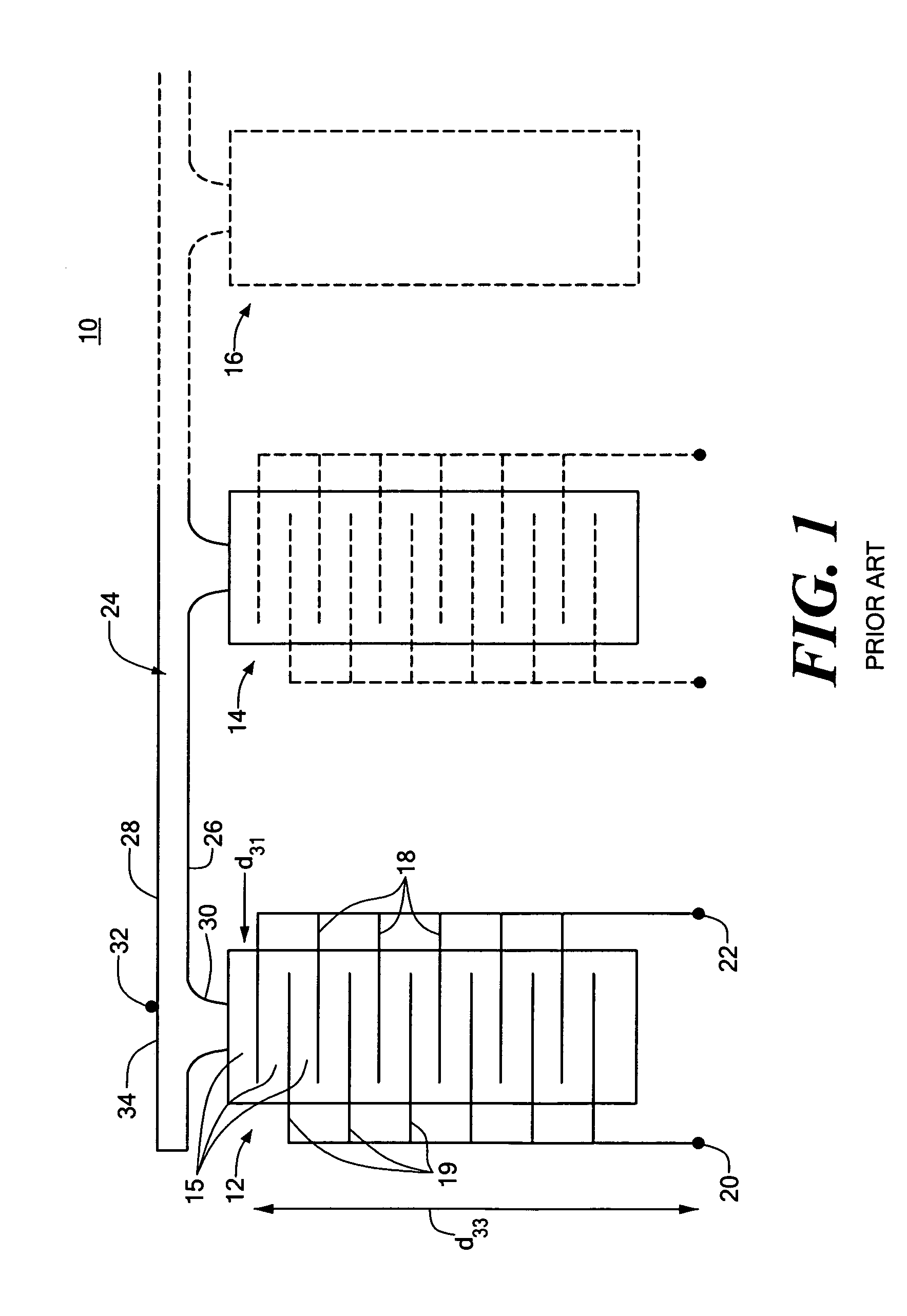
[0027] There is shown in FIG. 1, a longitudinal electrodisplacive actuator array 10, including a plurality of actuators, 12, 14, 16, each of which is constructed as explained with respect to actuator 12, which is formed in a laminar construction comprising layers of a ferroic material, that is, a ferroelectric or ferromagnetic material. For example, it may be a ferroelectric material, such as, lead magnesium niobate (PMN); a ceramic material which exhibits electrostrictive characteristics. Actuator 12 includes a plurality of layers of the electrostrictive ceramic PMN of layers 14 of the e...


PUM


Abstract

A transverse electrodisplacive actuator array for controlling the optical phasing of a reflective surface includes a support structure; a plurality of electrodisplacive actuator elements extending from a proximate end at the support structure to a distal end; each actuator element including at least one addressable electrode and one common electrode spaced from the addressable electrode and extending along the direction of said proximate and distal ends along the transverse d31 strain axis; a reflective member having a reflective surface and a mounting surface mounted on the actuator elements; and a plurality of addressable contacts and at least one common contact for applying voltage to the addressable and common electrodes to induce a transverse strain in addressed actuator elements to effect an optical phase change in the reflective surface at the addressed actuator elements.

Description

FIELD OF THE INVENTION [0001] This invention relates to a transverse electrodisplacive actuator array for controlling the optical phasing of a reflective surface. BACKGROUND OF THE INVENTION [0002] Historically, electroceramic actuators such as piezoelectric lead-zironcate titanate (PZT) or electrostrictive lead-magnesium-niobate (PMN) were operated in a configuration such that the electrodes were connected electrically in parallel and the ceramic layers were connect mechanically in series. See U.S. Pat. No. 4,932,119. The longitudinal strain component was utilized to produce the actuator displacement and force. For electric fields of 30V / mil (1×10⁶ V / mm), less than 0.10_m per layer was attained for a 0.007 inch active layer thickness (consistent with a strain of 800 ppm). To attain free actuator strokes approaching 10-m nearly 100 active layers were required to produce the necessary electrostrain. The net result is a complex mutilayer actuator configuration which is very sensitive ...

Claims


Application Information

Patent Timeline
IPC IPC(8): G02B5/08G02B26/00G02B26/08G02F1/03G02F1/07H01L27/20
CPCH01L41/0831G02B26/0825H10N30/501
Inventor EALEY, MARK A.
Owner NORTHROP GRUMMAN SYST CORP
Why Eureka
Try Eureka