High aperture LCD with insulating color filters overlapping bus lines on active substrate

a color filter and high aperture technology, applied in the field of high aperture lcd, can solve the problems of limited illumination, affecting the effect of insulating color filter, and not always desirable to have a shield electrode disposed along the length, so as to reduce the stress at the interface

Inactive Publication Date: 2005-05-26
LG DISPLAY CO LTD
View PDF40 Cites 10 Cited by
  • Summary
  • Abstract
  • Description
  • Claims
  • Application Information

AI Technical Summary

Benefits of technology

[0023] Surprisingly, it has been found that the thickness of the metal pixel electrode layers (e.g. ITO) should be from about 300 Å-900 Å (preferably about 600 Å) in this invention in order to reduce the interface stress between the pixel electrodes (e.g. ITO) and the color filters.

Problems solved by technology

As a result, either display luminance is limited or backlight power consumption is excessive, thereby precluding or limiting use in certain applications.
Unfortunately, it is not always desirable to have a shield electrode disposed along the length of the signal lines as in Suzuki due to production and cost considerations.
The disposition of the shield layer as described by Suzuki requires extra processing steps and thus presents yield problems.
Unfortunately, the method of making this display as well as the resulting structure are less than desirable because: (i) chemical vapor deposition (CVD) is required to deposit the silicon oxide or silicon nitride insulating film; (ii) silicon oxide and silicon nitride are not photo-imageable (i.e. contact holes or vias must be formed in such insulating layers by way of etching); and / or (iii) the dielectric constants of these materials are too high and thereby render the LCD susceptible to cross-talk problems.
As a result of these problems, the manufacturing process is both expensive and requires more steps than would be otherwise desirable.
With respect to CVD, this is a deposition process requiring expensive equipment.
Furthermore, if the color filters are on the passive substrate, as they typically are, alignment of the active and passive plates is difficult and requires expensive equipment and expertise.
The provisions of the black matrix and color filters on the substrate opposite the active matrix is, of course, costly, time consuming, and requires numerous manufacturing steps.
As discussed above, this also requires difficult and time consuming alignment steps.
While this design work well and achieves superior results, it unfortunately, in practice, requires each of: (i) providing the transparent polymer insulating layer on the active substrate; (ii) providing color filters on the opposite substrate; (iii) providing a black matrix on the color filter substrate; (iv) very accurate plate-to-plate (i.e. substrate-to-substrate) alignment; and (v) the process steps required for (ii)-(iv) above.

Method used


Image

  • High aperture LCD with insulating color filters overlapping bus lines on active substrate
  • High aperture LCD with insulating color filters overlapping bus lines on active substrate
  • High aperture LCD with insulating color filters overlapping bus lines on active substrate

Examples


Embodiment Construction

[0047] Referring now more particularly to the accompanying drawings in which like reference numerals indicate like parts throughout the several views.

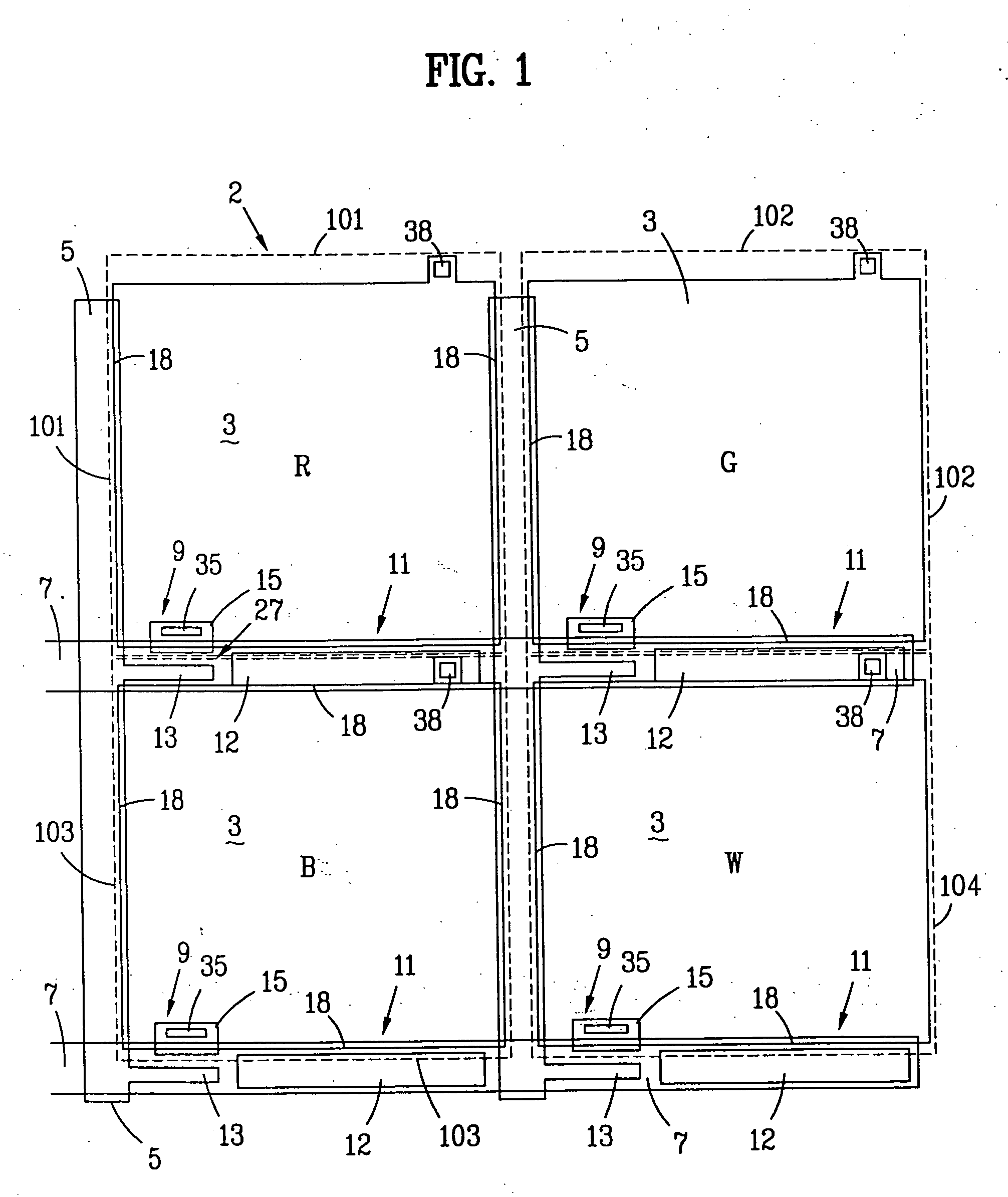
[0048]FIG. 1 is a top view of four different colored pixels (red, green, blue, and white) in an array on the active plate of an active matrix liquid crystal display (AMLCD) 2 according to an embodiment of this invention. This particular portion of the display includes an array pixel electrodes 3, drain address lines 5, gate address lines 7, an array of four thin-film transistors (TFTs) 9, auxiliary storage capacitors 11, and finally insulating color filters 101-103 (the peripheries of these color filters are illustrated in broken or dotted lines) and optional substantially clear polymer layer 104. The color layer 104 defines white pixel(s). Each storage capacitor 11 is defined on one side by a gate line 7 and on the other side by an independent storage capacitor electrode 12. Storage capacitor electrodes 12 are formed along with drain...


PUM

PropertyMeasurementUnit
dielectric constantaaaaaaaaaa
angleaaaaaaaaaa

Abstract

A high aperture active matrix liquid crystal display (AMLCD) includes pixel electrodes in respective pixels which overlap adjacent address lines. The color filters are formed on the active substrate in a manner such that the filters also overlap the address lines and function as an insulating layer between the pixel electrodes and address lines in the areas of overlap. Accordingly, line-pixel capacitances are reduced and the resulting AMLCD is easier to manufacture. The total number of process step in manufacturing is reduced, and plate-to-plate (active to passive plate) alignment is much easier and less important.

Description

[0001] This application is a continuation-in-part (CIP) of U.S. Ser. No. 08 / 630,984, filed Apr. 12, 1996; and a CIP of Ser. No. 08 / 470,271, filed Jun. 6, 1995 entitled LCD WITH. INCREASED PIXEL OPENING SIZES, and a CIP of Ser. No. 08 / 671,376, filed Jun. 27, 1996, the disclosures of which are all hereby incorporated herein by reference. Also, this application is related to commonly owned U.S. Pat. No. 5,641,974, and Ser. No. 08 / 832,345, the disclosures of which are incorporated herein by reference.[0002] This invention relates to a liquid crystal display (LCD) having an increased pixel aperture ratio and different colored polymer filters. More particularly, this invention relates to a liquid crystal display including an array of TFTs wherein photo-imageable color filters having contact vias or apertures disposed therein are located on the active substrate between the address lines and pixel electrodes so that the pixel electrodes and color filters may both be permitted to overlap at ...

Claims


Application Information

Patent Timeline
Patent Type & Authority Applications(United States)
IPC IPC(8): G02F1/1362G02F1/1368H01L21/336H01L21/77H01L21/84H01L27/12H01L27/146H01L29/786
CPCG02F1/136213G02F1/136227G02F1/1368G02F2202/42H01L27/1248H01L27/14603H01L29/66765H01L29/78636H01L27/12
Inventor ZHONG, JOHN Z.Z.BOER, WILLEM DEN
Owner LG DISPLAY CO LTD
Why Eureka
Try Eureka