Multiple bore termination system

a termination system and multi-bore technology, applied in the direction of couplings/cases, coupling device connections, electrical equipment, etc., can solve the problems of difficult task, difficult procedure, and inability to perform procedures using hot sticks, etc., to achieve convenient and convenient operation, reduce the effect of the tap plug and the effect of reducing the tap plug

Active Publication Date: 2006-12-21
RICHARDS MFG CO INC
View PDF7 Cites 10 Cited by
  • Summary
  • Abstract
  • Description
  • Claims
  • Application Information

AI Technical Summary

Benefits of technology

[0021] The present invention relates to a novel cable termination system for terminating a cable to an apparatus, such as a transformer or high voltage switch, within a housing. The present invention is a simple, economical system that terminates a cable that is connected to a coupling device, such as a metallic lug, to an apparatus. The present invention is preferably directed to a system that may terminate a cable to an apparatus, with a means of testing and grounding the connection or connecting two “through-cables” and a third cable tap, according to methods known in the art, require the use of a separate component or connecting plug, such as but not limited to, a loadbreak reducing tap plug, a dead break reducing tap plug, a reducing tap well, insulating plug and a connecting plug.

Problems solved by technology

However, the threading process can create significant field problems.
However, because the assembly of the housing and the first mating device lacks a stud holding the metallic lug, the housing and the first mating device together, each element must be properly aligned and balanced to ensure proper insertion of the stud through the aperture of the metallic lug and into the cavity of the component of the first mating device.
The bolt must be inserted in the proper direction and angle to properly hold the assembly in place, which can become a difficult task at a several feet distance.
However, if the first mating device is an LRTP or T OP II™, it is already assembled into the lug aperture, and if the first mating device is an RTW, RTP, CP (Connecting Plug) or an insulating plug, such as a BIP, this tightening procedure would not be performed using a hot stick or a long instrument.
One potential problem that may arise is that if a sleeve of an LRTP or T OP II™ is threaded, it may cross thread with the threading in the metallic lug, thereby failing to create a secure and stable electrical connection.
This problem is aggravated by the fact that the installer is performing the task blind, without being able to see the threading.
Additionally, proper alignment of the threads can be very difficult because of the weight of the cable.
On top of the fact that the operation cannot be viewed and the weight of the cable, the lineman must force the load break reducing tap plug forward to overcome the rubber interference while trying to engage the thread, creating potential problems.
Alternatively, if a product such as a connecting plug, reducing tap well, reducing tap plug, or insulating plug, which do not thread into the metallic lug is used, the installer must force the mating device into the elbow while simultaneously pushing the elbow onto the bushing or Connecting Plug, potentially creating difficulties during installation.
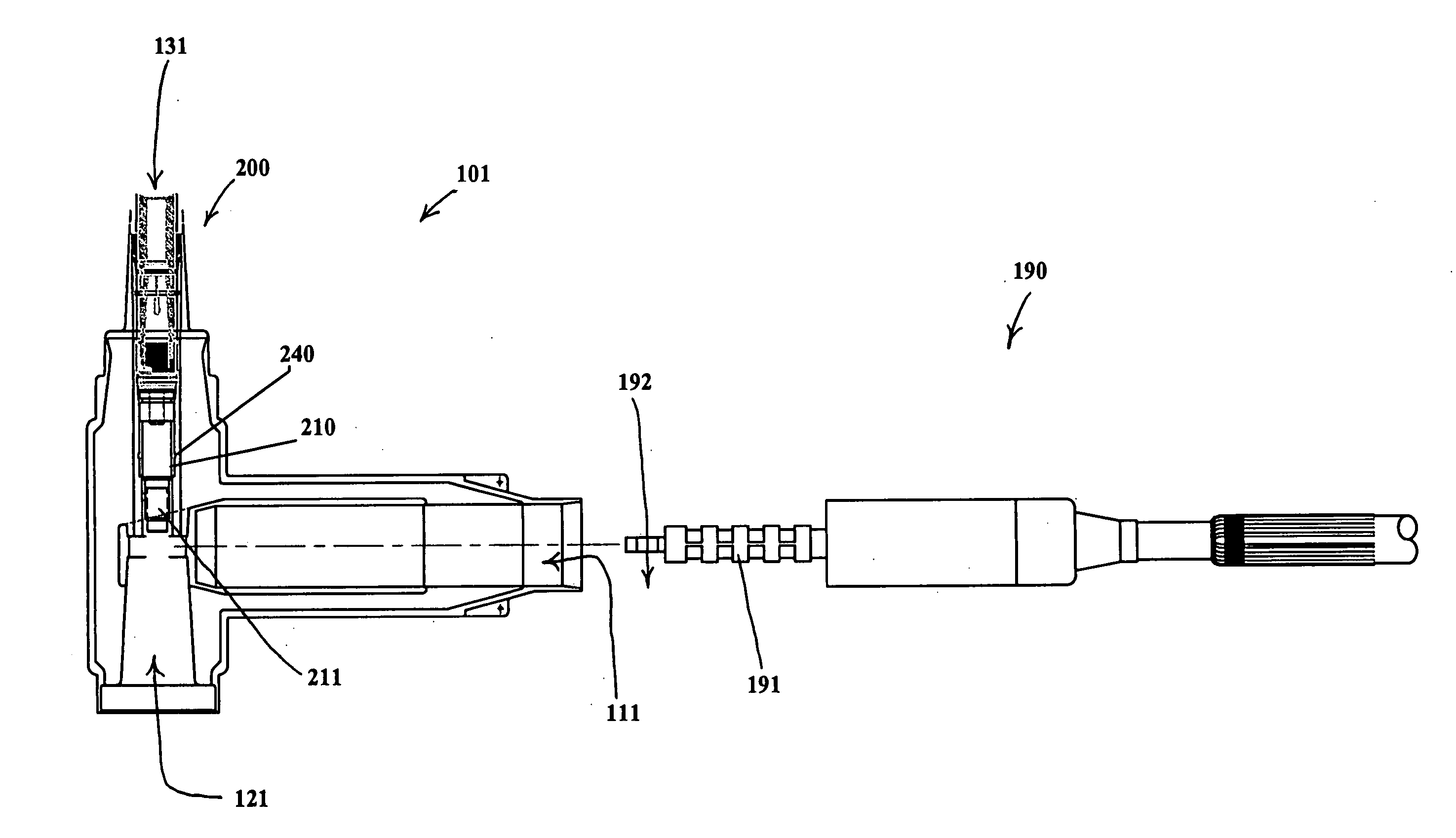
Another potential problem with the commonly known connectors and methods of connecting an electrical cable to an apparatus is the difficulty in connecting the cable and apparatus via separate components, for example, reducing tap plugs, connecting plugs, reducing tap wells, and the like.
Therefore, the three separate elements, the cable assembly, the housing and the separately molded component, which can be cumbersome and heavy, must be properly positioned and held in that position during this process.
Therefore, in order for this separately molded mating device to be properly inserted within the housing, elements such as the guide and the threaded portion are needed, which renders the device complex with multiple parts that also can increase the cost.
Additionally, because the three separate elements must be simultaneously held in position, the process can be cumbersome and difficult.
In addition, because the mating device is a separately molded component, it suffers from some of the same problems of the other prior art devices discussed above.
Luzzi, however, does not disclose how to connect the termination system to a second device via the second bore, but is directed to an elbow having an insulating plug at the second bore.
Furthermore, Luzzi does not provide for safety testing or grounding.
Sankey, however, does not include a movable piston and therefore does not have loadbreak capabilities for safety testing or a fault close capability for safe grounding of the system.
Accordingly, the elbow or cap connected to the opposite side of the first mating device cannot be removed when the cable is live without potentially causing an explosion in the termination system.
This can be especially problematic because the termination system can provide a perception that the device does have loadbreak and fault close capabilities.
Furthermore, if a cap was the mating part and was successfully removed, there is no safe way to ground the assembly without load break components inside the LRTP.
This also can hinder current flow between the cable and the connecting member, and therefore the terminal.
Furthermore, the contact assembly is directly inserted into the housing through a passage, which produces a risk of contaminating the inside bore of the device which can lead to product failure.
Additionally, the prior art devices, because they require separated molded components, can result in an undesirably long stack height after assembly because of the interfaces of each element, such as the interface of the elbow in combination with the interface of the separately molded component.

Method used


Image

  • Multiple bore termination system
  • Multiple bore termination system
  • Multiple bore termination system

Examples


Embodiment Construction

[0046] As required, a detailed illustrative embodiment of the present invention is disclosed herein. However, techniques, systems and operating structures in accordance with the present invention may be embodied in a wide variety of forms and modes, some of which may be quite different from those in the disclosed embodiment. Consequently, the specific structural and functional details disclosed herein are merely representative, yet in that regard, they are deemed to afford the best embodiment for purposes of disclosure and to provide a basis for the claims herein, which define the scope of the present invention. The following presents a detailed description of a preferred embodiment of the present invention.

[0047] Referring initially to FIG. 1, shown is a typical elbow housing for a prior art elbow housing termination system. As depicted, housing 100 comprises a first bore 110, which is perpendicular to a second bore 120 and a third bore 130. Typically, a cable is inserted in first...


PUM


Abstract

A cable termination housing for terminating a cable to one or more devices includes a bore for receiving a device mating portion, a component portion integrally formed within the housing, the component portion having a fastener that is slidable between a retracted position wherein fastener does not extend into the lug aperture of the cable assembly and an extended position wherein the fastener extends into the lug aperture. Preferably, the fastener is rotatable while in its extended position so as to couple with the device mating portion.

Description

CROSS-REFERENCE TO RELATED APPLICATIONS [0001] This application claims the benefit of U.S. Provisional Application Ser. No. 60 / 667,387 filed on Apr. 1, 2005, and U.S. Provisional Application Ser. No. 60 / 686,081 filed on May 31, 2005, both of which are entitled “MULTIPLE BORE TERMINATION SYSTEM”, which are both hereby incorporated in their entirety by reference.TECHNICAL FIELD OF THE INVENTION [0002] The present invention relates to a multiple bore termination system that may be used for terminating electrical cables. More particularly, the present invention relates to a multiple bore termination system for connecting an electrical cable to an apparatus, such as a transformer or high voltage switch, and is ideally suited for use with electrical cables and / or electrical equipment. BACKGROUND OF THE INVENTION [0003] Existing cable termination systems for connecting a cable to an apparatus, two cables or two feeder cables with a tap are known in the art. A termination system typically i...

Claims


Application Information

Patent Timeline
Patent Type & Authority Applications(United States)
IPC IPC(8): H01R13/53
CPCH01R13/53H01R11/11
Inventor LUZZI, GLENN J.
Owner RICHARDS MFG CO INC
Why Eureka
Try Eureka