Shock absorbing material

a technology of shock absorption and material, applied in the direction of shock absorption, elastic damper, pedestrian/occupant safety arrangement, etc., can solve the problems of poor shock absorption ability, inability to provide optimal structure utilizing the characteristics of polyurethane foam, and degraded visibility range, so as to reduce the head injury criteria and good shock absorption ability

Inactive Publication Date: 2002-01-29
BRIDGESTONE CORP
View PDF8 Cites 10 Cited by
  • Summary
  • Abstract
  • Description
  • Claims
  • Application Information

AI Technical Summary

Benefits of technology

Accordingly, a first object of the present invention is to provide a shock absorbing material for an automobile having extremely good shock absorbing ability and which is suitable for absorbing shock energy from a pillar impacting a head of a passenger including a driver in a cabin at the time of a crash of an automobile, or the like, and reducing head injury criteria.

Problems solved by technology

That disclosed in Japanese Unexamined Utility Model Publication No. 6-42437 uses a rigid polyurethane foam as the protecting material for shocks to the head; however, since it has a composite structure with a hollow-shaped resin part (trim), the compression stress of the rigid polyurethane foam must be as low as 0.2 to 2 kg / cm.sup.2, and thus the optimum structure utilizing the characteristics of the polyurethane foam cannot be provided.
Moreover, since the irregular shape is for reducing the weight and maintaining strength thereof, but is not for improving the shock absorbing ability, the shock absorbing ability cannot be improved.
Moreover, regarding the concave shape, since the part contacting the car body is extremely thin, the pad must be thick in order to yield sufficient shock absorbing ability, and thus problems arise in that due to reduced car interior space in the automobile, comfort, convenience in entering and exiting, and visibility range are degraded.
However, the soft or rigid polyurethane foam itself used as the cushion material does not have an irregular shape to improve performance, but has a concave shape only at the mounting part.
Moreover, it is mentioned that a sufficient shock absorbing ability cannot be achieved with an overall excessively high or low rigidity, but a specific numerical value or range is not described, and thus it is difficult to ensure that good shock absorbing ability can be obtained.
Therefore, use thereof as a head protecting material is limited.
For example, it is not suitable for side rails, or the like.
Moreover, it is mentioned that it has a thickness necessary for absorbing shock, but specific thicknesses or hardnesses are not described, and thus it is difficult to ensure that good shock absorbing ability can be obtained.
If a force is applied to a face contact part locally, particularly by a spherical object such as the head of a dummy, the force is concentrated in the beam part between ribs, as disclosed in Japanese Unexamined Patent Publication No. 7-16867, comprising a bead-like molded resin, and thus sufficient shock absorbing ability cannot be obtained.
If the shaped part is made of a rigid polyurethane foam, the beam part will break.
As a result, a distance effective for absorbing energy cannot be obtained.
Those disclosed in Japanese Unexamined Patent Publication Nos. 8-142234 and 8-295194 have a thin lattice-like rib of 0.6 to 1.2 mm, and furthermore, it is disadvantageous in that because a polyolefin resin rib absorbs energy basically by the bending of the rib, shock absorbing ability is highly dependent on the direction of the shock.
As mentioned above, none of the conventional shock absorbing materials obtaining optimum shock absorbing ability by actively designing the shape of the shock absorbing material.
As a result, it has never been possible to provide a high shock absorbing ability by the shock absorbing material itself.
The conventional head protecting material mounting method involves the following problems.
Although the mounting operation itself can be easier by mounting with an adhesive tape compared with the case of using an adhesive, since the head protecting material is made of a relatively hard material and thus cannot follow the deformation of the mounted surface, the head protecting material can easily peel and fall off.
That is, if the head protecting material is mounted to a part of a flat and wide area like the rear surface of the ceiling material, when the part is deformed by twisting during transportation, the adhesive surface peels and falls off due to inability to conform to the deformations of the hard head protecting material.
Moreover, in assembling a part mounted with the head protecting material, such as the ceiling material with a car body, since the head protecting material projects from the part, such as the ceiling material for the thickness thereof as a level difference, when the projecting head protecting material contacts the car body, or the like, the head protecting material falls off from the part also in this case due to inability of the adhesive surface to follow the deformation for the hardness of the head protecting material.
On the other hand, in the case of mounting with an adhesive, since the part needs to be left for about one day after application of an adhesive in a method of using an aqueous adhesive, a long mounting operation time is required, and thus it is not practical.
Moreover, since the head protecting material needs to be fixed and held for 20 to 30 seconds after application when a hot melt adhesive is used, and an standing time is required after application of an adhesive in the case of a solvent adhesive, both require a large number of bonding steps, and thus are difficult to execute.
Moreover, since both the hot melt adhesive and the solvent adhesive become adhesive by hardening and the adhered to surface becomes hard, the adhered to surface cannot conform to the deformation when there is deformation during transportation or a crash of the car body so that a problem arises in which the head protecting material falls off, as in the case of the adhesive tape.

Method used


Image

  • Shock absorbing material
  • Shock absorbing material
  • Shock absorbing material

Examples


example 1

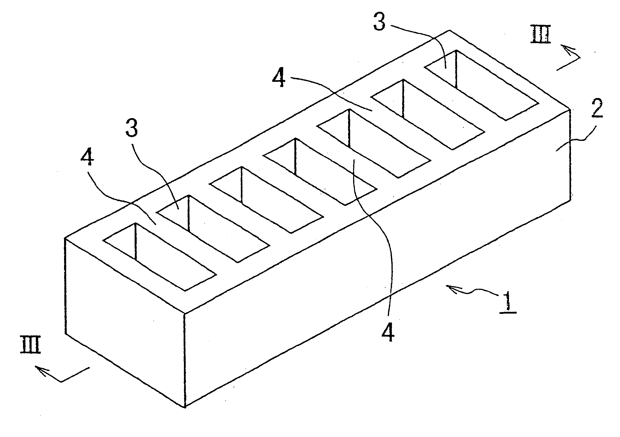
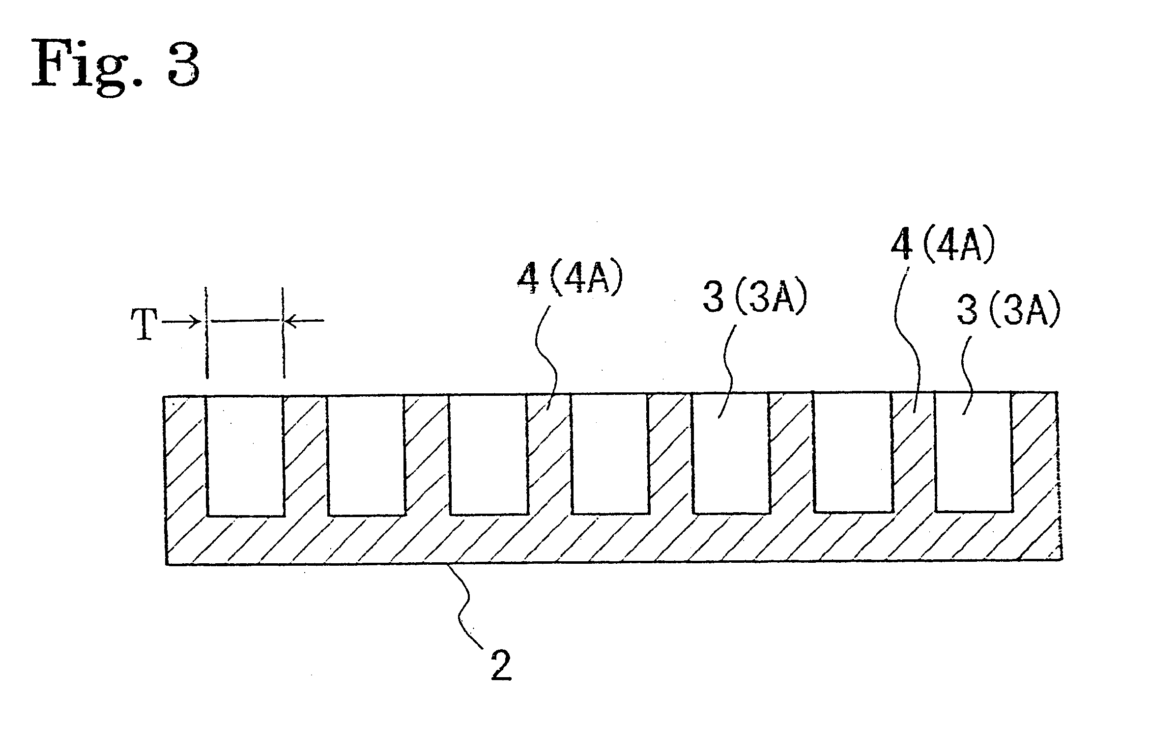
A shock absorbing material with the shape shown in FIGS. 1 and 3 was produced from a rigid polyurethane foam having a compression stress of 15 kg / cm.sup.2. The shock absorbing material comprises a planar member having an external size of 210 mm (in the longitudinal direction).times.60 mm (in the lateral direction).times.20 mm (in the vertical direction), with concave portions of 50 mm.times.10 mm.times.10 mm (depth) provided parallel with an arrangement pitch of 15 mm with a 5 mm thickness T of the wall parts, and a 28% excavation ratio.

The head injury criteria were measured for the shock absorbing material. Results are shown in Table 1.

example 2

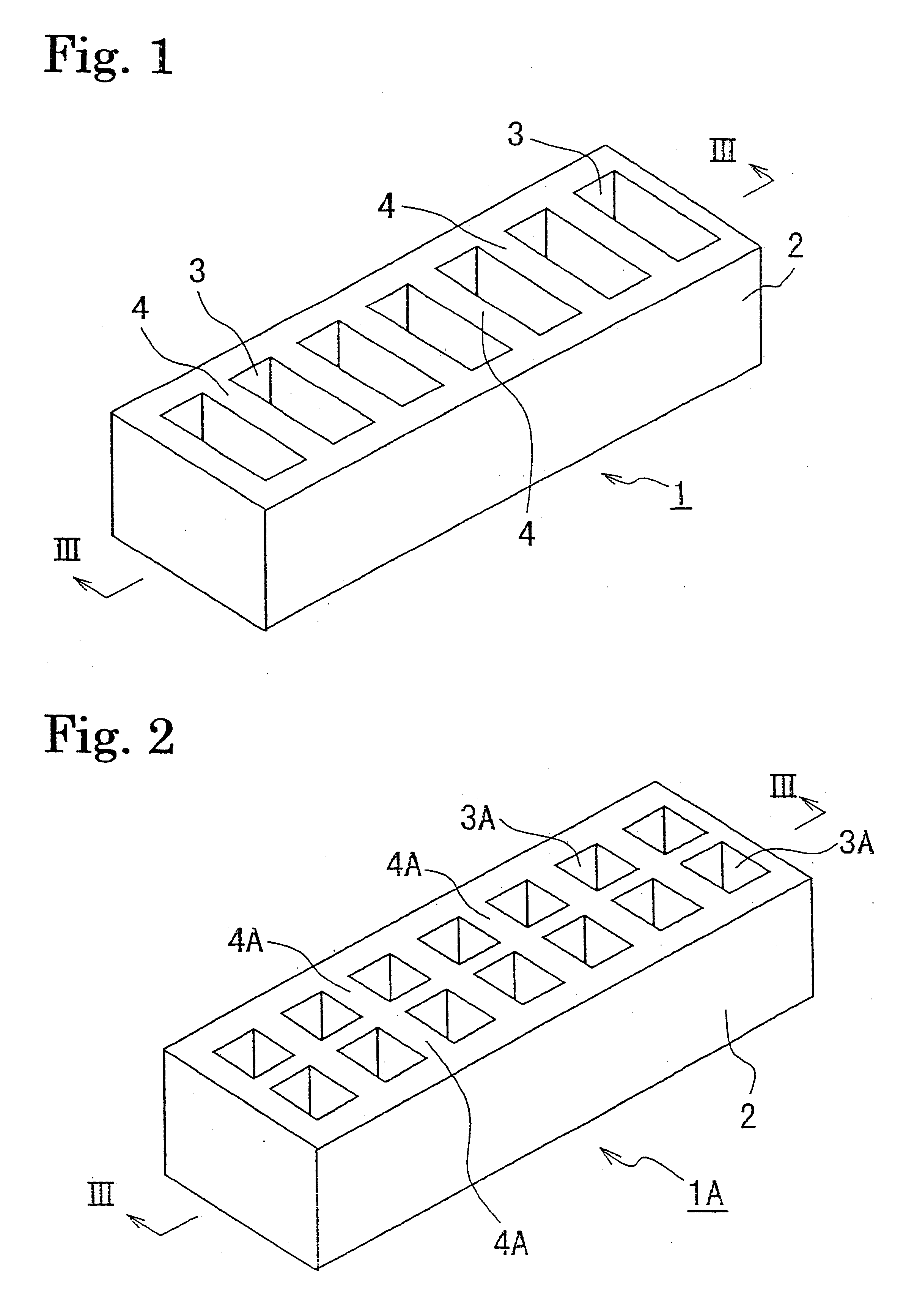
A shock absorbing material was produced in the same manner as example 1 except that the concave portions were formed so as to have the with of the wall part and the excavation ratio of the values shown in Table 2, and the head injury criteria were measured. Results are shown in Table 2.

example 3

Ahead protecting material made of a rigid polyurethane foam 60 mm.times.450 mm.times.20 mm with an adhesive tape comprising a base material having a thickness of 3 mm made of a soft polyurethane foam with a 0.02 g / cm.sup.3 density having an acrylic adhesive material adhesive layer (thickness: 0.06 mm) formed on both sides thereof, attached as shown in FIG. 12A, was mounted to a ceiling material for automobiles at the position shown in FIG. 13A. After mounting the head protecting material, the ceiling material was transported and assembled into a car body.

When a head protecting material was mounted with an adhesive tape comprising a base material such as non-woven fabric, paper, plastic film, or the like, with an adhesive material applied thereon for forming an adhesive layer, falling off of the head protecting material occurred at the time of transportation and assembly. However, in this embodiment, even when the ceiling material was deformed during transportation or impact with ano...


PUM

PropertyMeasurementUnit
widthaaaaaaaaaa
thicknessaaaaaaaaaa
thicknessaaaaaaaaaa

Abstract

A shock absorbing material for automobiles, having extremely good shock absorbing properties, capable of absorbing shocks applied to a passenger in a car at the time of a crash, or the like, and reducing the head injury criteria, comprising a rigid polyurethane foam having a compression stress of 3 kg/cm2 or more, with concavities arranged on at least one planar surface. In order to mount the head protecting material to a ceiling material, a trim, a car body, or the like, easily and securely, the head protecting material is mounted to the ceiling material, or the like, with an adhesive sheet comprising a base material made of a foam material with an adhesive layer formed thereon.

Description

BACKGROUND OF THE INVENTION AND RELATED ART STATEMENTThe present invention relates to a shock absorbing material, and in particular relates to a shock absorbing material for automobiles, suitable for reducing head injury criteria by absorbing shock energy imparted to the heads of passengers in the car interior at the time of a crash.As shock absorbing materials for automobiles, the followings have been proposed conventionally:i) Japanese Unexamined Utility Model Publication No. 6-42437 discloses one comprising a pillar guard of a resin with a hollow shape, with a rigid polyurethane foam provided in a hollow part thereof for absorbing shock.ii) Japanese Unexamined Patent Publication No. 8-2358 discloses a pad material comprising a foam material or a rubber material.iii) Japanese Unexamined Patent Publication No. 8-72642 discloses one comprising a cushion member made from a rigid polyurethane foam covered with a shape-protecting material made of a sheet metal with a concave portion fo...

Claims


Application Information

Patent Timeline
Patent Type & Authority Patents(United States)
IPC IPC(8): B60R21/04C09J7/02F16F7/12C09J7/26
CPCB60R21/04C09J7/0289F16F7/12F16F7/121Y10T428/24479B60R2021/0442C09J2421/00C09J2421/006C09J2423/006C09J2433/00C09J2475/006Y10T428/28Y10T428/24496Y10T156/1089Y10T428/24678Y10T428/24512B60R2021/0414C09J7/26Y10T428/249953
Inventor TADA, SHINTABATA, KEIICHIROHORIMATSU, TOSHIYUKI
Owner BRIDGESTONE CORP
Why Eureka
Try Eureka