Impact-absorbing member for vehicles

a technology for impact absorption and vehicles, applied in the direction of shock absorption, elastic dampers, bumpers, etc., can solve the problems of large deformation space required for the bumper fascia, disadvantage in fuel consumption, and large weight, and achieve good impact energy absorption function, effective protection, and increased impact load

Inactive Publication Date: 2007-04-19
SUMITOMO RIKO CO LTD
View PDF6 Cites 9 Cited by
  • Summary
  • Abstract
  • Description
  • Claims
  • Application Information

AI Technical Summary

Benefits of technology

[0043] The impact-absorbing member of the present invention consists of a molded article formed in prescribed shape of a resin material and comprises a plurality of tabular ribs spaced apart from one another and arranged in parallel so as to extend in the direction orthogonal to the input direction of impact load, and a tubular member having an impact load input portion situated to the front side of the tabular ribs in the impact load input direction for receiving input impact load, and multiple pairs of tabular holding portions connected respectively at a first end thereof to the two ends of the tabular ribs and disposed on the diagonal so as to approach one another at increasing distance away from the first end in the direction perpend...

Problems solved by technology

However, in order to prevent damage to the impacted object, the bumper fascia must undergo a sufficient level of elastic deformation, and a correspondingly large deformation space for the bumper fascia is required.
However, since this energy absorbing member is fabricated of hollow aluminum alloy, it will tend to have higher weight as compared to resin materials, which represents a disadvantage in terms of fuel consumption.
However, with these expanded elastomers, a relatively flat characteristics curve is observed in a graph representing the relationship of load and the level of displacement when impact load is input, so while energy absorption efficiency is relatively good, there is the problem of appreciable collapse residuum and poor space efficiency.
However, this rib structure has the problem that, since ...

Method used


Image

  • Impact-absorbing member for vehicles
  • Impact-absorbing member for vehicles
  • Impact-absorbing member for vehicles

Examples


Embodiment Construction

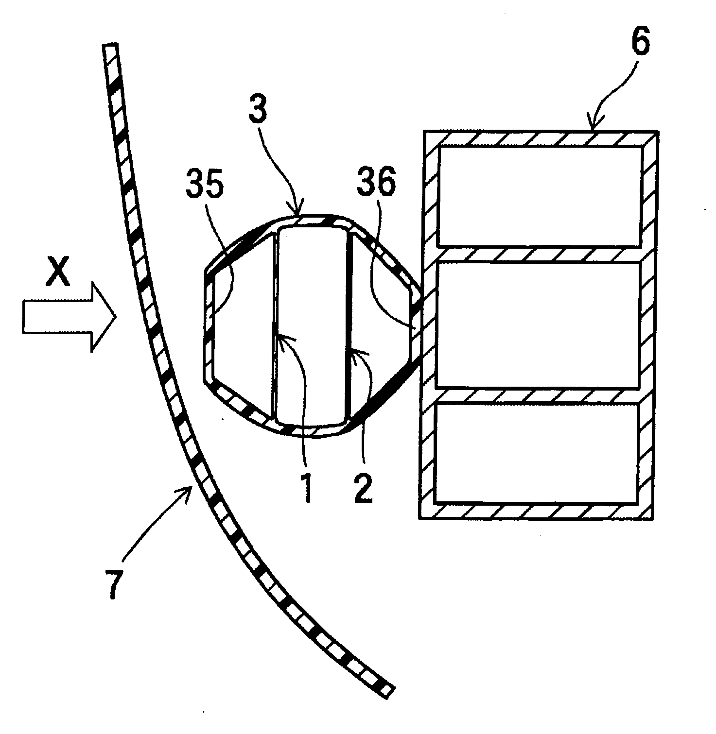
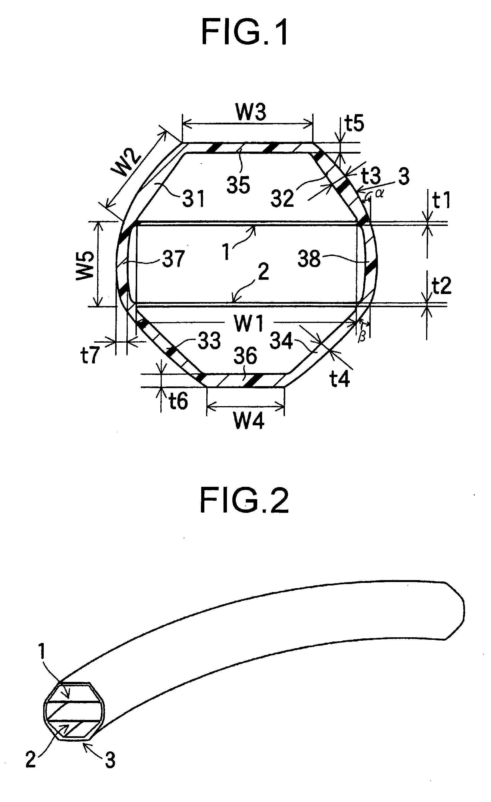
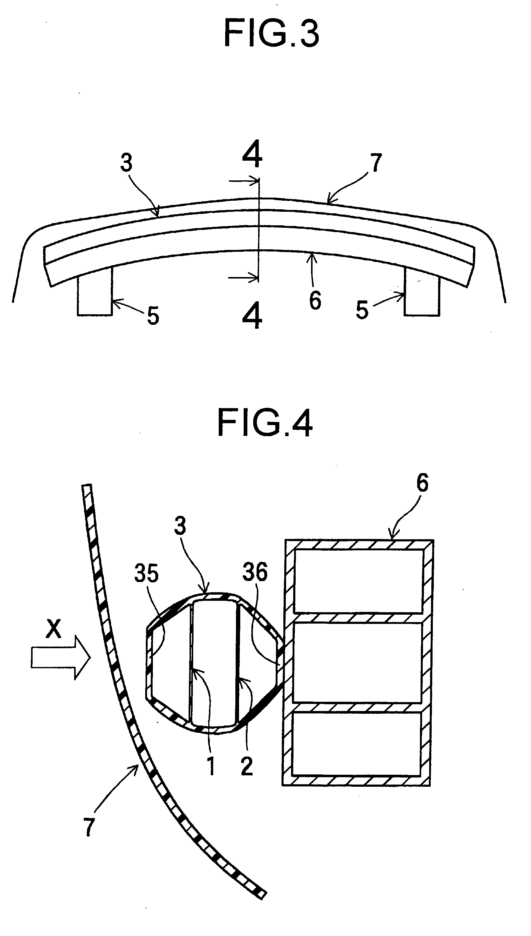
[0059] The specific embodiments of the invention will be described hereinbelow with reference to the drawings. FIG. 1 is a cross sectional view taken in the axis-perpendicular direction of an automotive impact-absorbing member as a preferred embodiment of an impact-absorbing member according to this embodiment of the invention, and FIG. 2 is a perspective view of the automotive impact-absorbing member.

[0060] As shown in FIG. 1 and FIG. 2, the automotive impact-absorbing member of this embodiment of the invention is an elongated tubular molded article integrally formed of resin material, and is composed of two, i.e. first and second tabular ribs 1, 2 spaced apart from one another and arranged in parallel so as to extend in the direction orthogonal to the input direction of impact load, and a tubular member 3 having a pair of first tabular holding portions 31, 32 serving as load transmitting members, a pair of second tabular holding portions 33, 34 serving as load transmitting member...


PUM

PropertyMeasurementUnit
Thicknessaaaaaaaaaa
Tensile propertiesaaaaaaaaaa
Shapeaaaaaaaaaa

Abstract

An impact-absorbing member includes tabular ribs extending in a direction orthogonal to an impact load input direction, and disposed spaced apart in the impact load input direction and parallel to one another; and a load transmitting member connected with width-wise opposite ends of the respective tabular ribs to extend between the tabular ribs on a diagonal with respect to the impact load input direction, for transmitting to each of the tabular ribs an impact load in a form of tensile load directed in a lateral direction, wherein differing levels are established for at least one of: tensile stiffness in the plurality of tabular ribs per se; and transmission efficiency of the tensile load by the load transmitting member, so that load-deformation characteristics of some of the plurality of tabular ribs differ in the impact load input direction.

Description

INCORPORATED BY REFERENCE [0001] The disclosure of Japanese Patent Application No. 2005-280301 filed on Sep. 27, 2005 including the specification, drawings and abstract is incorporated herein by reference in its entirety. BACKGROUND OF THE INVENTION [0002] 1. Field of the Invention [0003] The present invention relates to an impact-absorbing member for vehicles, which is suitable for use in a car bumper, for absorbing impact during a collision in order to avoid personal injury. [0004] 2. Description of the Related Art [0005] To date, impact-absorbing members of various kinds have been employed in vehicle body frames, for the purpose of absorbing impact during a collision in order to avoid personal injury. For example, bumpers for absorbing impact energy during an automobile collision are attached to the front and rear of the vehicle body frame. Such bumpers are typically composed of metallic crush boxes attached with screws or the like to the vehicle body frame, a metallic bumper bea...

Claims


Application Information

Patent Timeline
IPC IPC(8): F16F3/08
CPCB60R19/18B60R2019/186F16F7/12F16F2224/0241
Inventor MURAYAMA, MASARUKATO, RENTARO
Owner SUMITOMO RIKO CO LTD
Why Eureka
Try Eureka