Magnets with varying magnetization direction and method of making such magnets

a magnetization direction and magnetic technology, applied in the field of permanent magnets, can solve the problems of weak magnetic force limiting the usefulness of conventional magnets, difficult rotation and translation of the magnet to change the direction of applied magnetic force, and large structure needed to support conventional magnets are expensive and cumbersome, so as to improve the magnetic properties, reduce the likelihood of interference, and the effect of small siz

Inactive Publication Date: 2006-03-23
STEREOTAXIS
View PDF9 Cites 61 Cited by
  • Summary
  • Abstract
  • Description
  • Claims
  • Application Information

AI Technical Summary

Benefits of technology

[0003] The present invention is a permanent magnet in which the magnetization direction varies to maximize the selected magnetic property of the magnet (e.g. field strength or gradient), and to a method of making such magnets. Generally, the magnet of the present invention comprises permanent magnets in which the magnetization direction at each point is selected to optimize the particular magnetic property. Thus in contrast to conventional permanent magnets in which the magnetization direction is uniform throughout, in the magnets of the present invention, the material at each point provides the optimum contribution to the desired magnetic property. This optimization means that a magnet of the present invention can be smaller and lighter than a conventional magnet, and yet sill provide equivalent magnetic force. This magnet is particularly useful in magnetic surgical procedures. The magnet allows smaller less cumbersome equipment to be used in to support and manipulate the magnet, and reduces the opportunity of interference with people and equipment in the procedure room.
[0005] Thus magnets of the present invention provide improved magnetic properties for a given weight and size over conventional permanent magnet. The magnets can be manipulated by smaller and less cumbersome equipment, and due to their smaller size are less likely to interfere with, or be interfered with by persons and equipment. The method of the present invention provides magnets of the present invention.

Problems solved by technology

However, the size of a conventional permanent magnetic that is needed to provide these strong magnetic forces limits their usefulness.
The structures needed to support massive conventional magnets are expensive and cumbersome.
Moreover because magnetic forces fall off rapidly (with the third power of the distance for magnetic fields and with the fourth power of the distance for magnetic gradients), the magnet must be very close to the point where the magnetic force is to be applied, making the rotations and translations of the magnet to change the direction of the applied magnetic force difficult.
In the special case of magnetic surgery applications, the movement of the magnet is also limited by imaging and life support equipment in the procedure room.

Method used


Image

  • Magnets with varying magnetization direction and method of making such magnets
  • Magnets with varying magnetization direction and method of making such magnets
  • Magnets with varying magnetization direction and method of making such magnets

Examples


Embodiment Construction

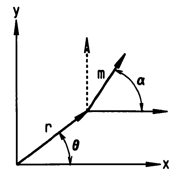
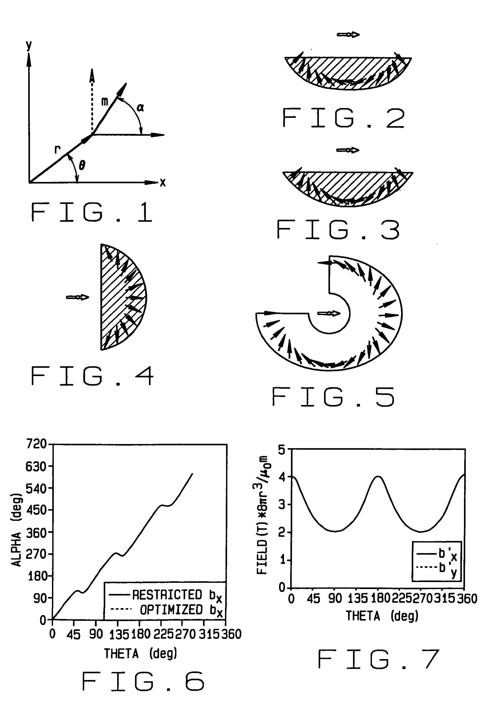
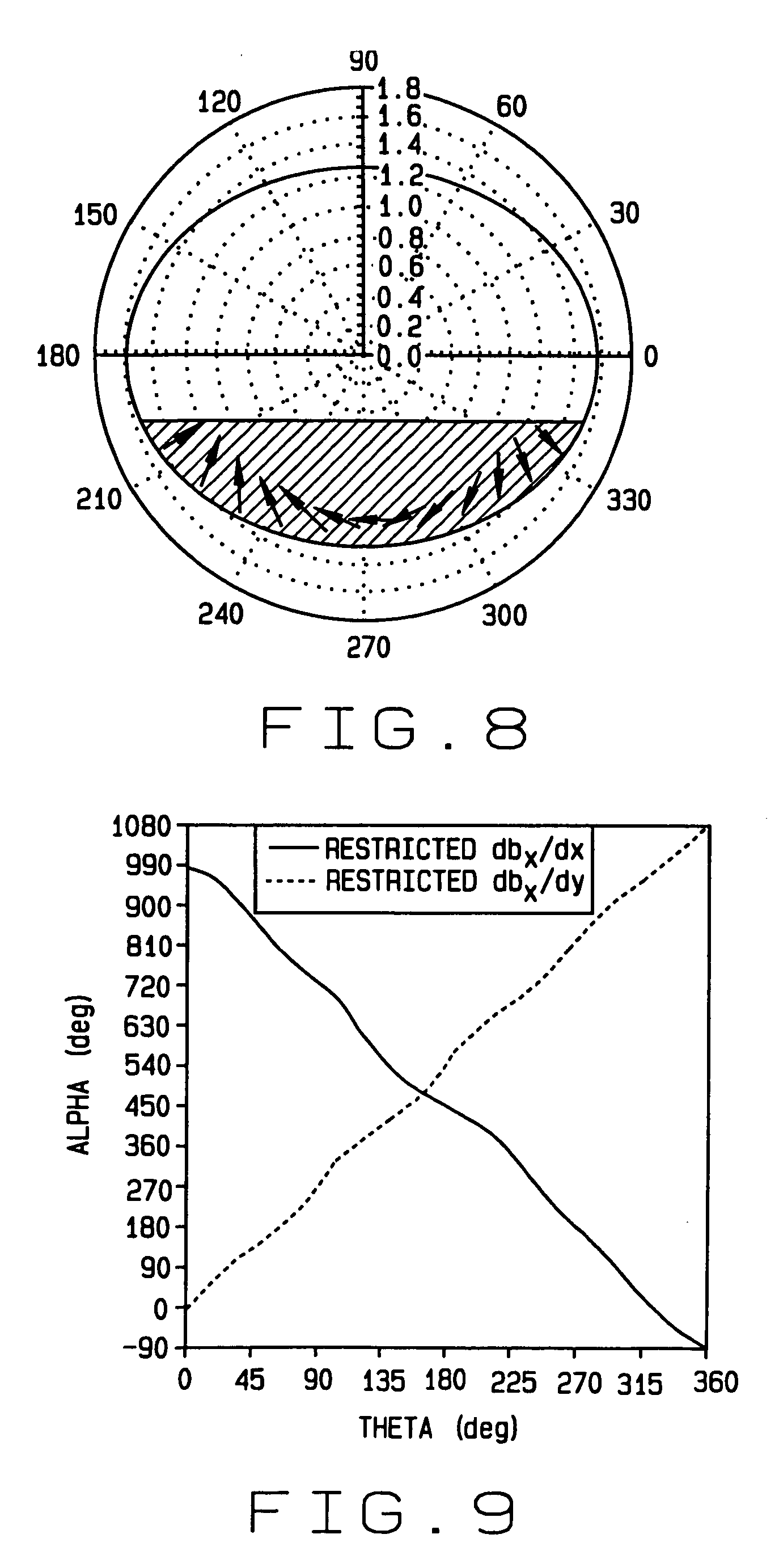
[0038] The magnets of the preferred embodiments of the present invention are permanent magnets in which the magnetization direction varies by location to provide magnets that optimize a selected magnetic field property at a selected location external to the magnet. These magnets may comprise a monolithic magnet in which the magnetization direction varies smoothly and continuously so that at each location, the magnetization direction is substantially in the direction that optimizes the selected magnetic property. Alternatively, these magnets may comprise a plurality of magnet segments, each with a magnetization that is substantially in the direction that optimizes the selected magnetic field property. These magnets can be used in any application, but are particularly useful for magnetic surgical applications.

[0039] The methods of making magnets of the preferred embodiments of the present invention provide for the simple construction of optimized magnets. The methods involve the arra...


PUM

PropertyMeasurementUnit
magnetic field propertyaaaaaaaaaa
magneticaaaaaaaaaa
magnetic fieldaaaaaaaaaa

Abstract

A permanent magnet in which the magnetization direction varies with location to optimize or restrict a magnetic field property in a selected direction at a selected point. The magnetic field property may be, for example, the transverse magnetic field, axial magnetic field, axial gradient of the transverse magnetic field, transverse gradient of the transverse magnetic field, axis gradient of the axial magnetic field, transverse gradient of the axial magnetic field, the product of the transverse magnetic field and the transverse gradient of the transverse magnetic field, the product of the transverse magnetic field and the axial gradient of the transverse magnetic field, the product of the axial magnetic field and the transverse gradient of the axial magnetic field, or the product of the axial magnetic field and the axial gradient of the axial magnetic field. The magnet may be formed of one or more segments in which the magnetization direction varies smoothly and continuously, or the magnet may be formed of a plurality of segments in which the magnetization direction is constant. A method of making and using such magnets is also disclosed.

Description

FIELD OF THE INVENTION [0001] This invention relates to permanent magnets, and in particular to a permanent magnet in which the magnetization direction varies to maximize a selected magnetic property of the magnet, and to methods of making such magnets. BACKGROUND OF THE INVENTION [0002] There are a number of applications, such as magnetic surgical applications, where it necessary to apply strong magnetic forces (i.e., magnetic fields and / or gradients). With recent advances in permanent materials, permanent magnets can provide strong magnetic forces for many of these applications. However, the size of a conventional permanent magnetic that is needed to provide these strong magnetic forces limits their usefulness. The structures needed to support massive conventional magnets are expensive and cumbersome. Moreover because magnetic forces fall off rapidly (with the third power of the distance for magnetic fields and with the fourth power of the distance for magnetic gradients), the mag...

Claims


Application Information

Patent Timeline
Patent Type & Authority Applications(United States)
IPC IPC(8): H01F7/02A61B17/00
CPCA61B17/00A61B2019/2253A61B2019/2257A61N2/00Y10T29/4902H01F7/0278H01F7/0294H01F13/003H01F41/028H01F7/0273A61B34/73A61B2034/731
Inventor CREIGHTON, FRANCIS M.
Owner STEREOTAXIS
Why Eureka
Try Eureka