Borehole caliper tool

a caliper tool and borehole technology, applied in the direction of instruments, electrical/magnetic measuring arrangements, survey, etc., can solve the problem of physical linking of the sensing device to a rigid arm, complicating the design and operation of the caliper tool

Inactive Publication Date: 2006-03-30
SCHLUMBERGER TECH CORP
View PDF31 Cites 21 Cited by
  • Summary
  • Abstract
  • Description
  • Claims
  • Application Information

AI Technical Summary

Problems solved by technology

As evident from conventional configurations, physically linking the sensing

Method used


Image

  • Borehole caliper tool
  • Borehole caliper tool
  • Borehole caliper tool

Examples


Embodiment Construction

[0014] In the following description, numerous specific details are set forth in order to provide a thorough understanding of the invention. However, it will be apparent to one skilled in the art that the invention may be practiced without some or all of these specific details. In other instances, well-known features and / or process steps have not been described in great detail in order to avoid obscuring the invention. The features and advantages of the invention may be better understood with reference to the drawings and discussions that follow.

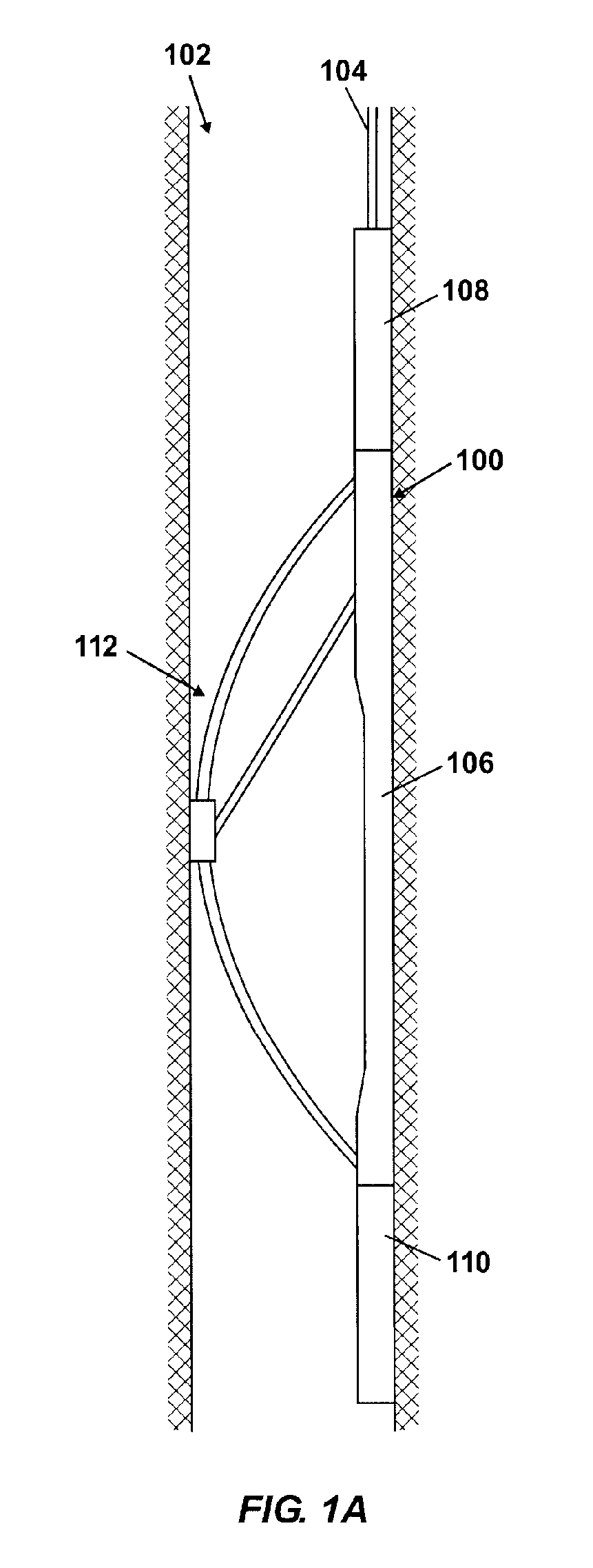
[0015]FIG. 1A shows a caliper tool 100 according to an embodiment of the invention deployed in a borehole 102. The caliper tool 100 measures and logs the diameter of the borehole 102 as it traverses the borehole 102. In FIG. 1A, the caliper tool 100 is suspended in the borehole 102 on the end of a logging cable 104. Alternatively, the caliper tool 100 could form a part of a downhole tool (not shown) that performs other downhole operations be...


PUM


Abstract

A borehole caliper tool includes a tool body and an arm coupled to the tool body. The arm is deflectable relative to the tool body. The caliper tool further includes a cam coupled to the arm such that a position of the cam changes as the arm deflects. The caliper tool further includes a proximity sensor for sensing the position of the cam, wherein the position of the cam provides an indication of the deflection of the arm relative to the tool body.

Description

BACKGROUND OF INVENTION [0001] Various caliper tools for gauging the diameter of a borehole are known in the art. In one example, a caliper tool includes one or more bow springs coupled to a tool body. When the tool body is disposed in a borehole, the bow spring engages the borehole wall. The bow spring flexes as the tool body traverses the borehole and the borehole diameter changes. The motion of the bow spring can provide an indication of the borehole diameter. In this case, a sensing device can be attached to the bow spring and used to monitor the motion of the bow spring. This is taught, for example, in U.S. Pat. No. 2,639,512. Some caliper tools further include one or more rigid arms coupled between the tool body and the bow spring. The rigid arm deflects as the bow spring flexes, and the motion of the rigid arm provides an indication of the borehole diameter. [0002] An electronic sensing device having a movable part is usually used to monitor the motion of the rigid arm. Typic...

Claims


Application Information

Patent Timeline
IPC IPC(8): G01B3/00
CPCG01B7/13E21B47/08
Inventor FREDETTE, MARK A.RITTER, SCOTTDUPREE, WADE D.
Owner SCHLUMBERGER TECH CORP
Why Eureka
Try Eureka