Twist-on connector

a technology of twisting and wire connectors, applied in the direction of electric cable installation, line/current collector details, connections effected by permanent deformation, etc., can solve the problems of excessive twisting of the upper end, and none provide a simple construction which allows for both manual attachment of the connector

Active Publication Date: 2006-04-06
THOMAS & BETTS INT INC
View PDF8 Cites 1 Cited by
  • Summary
  • Abstract
  • Description
  • Claims
  • Application Information

AI Technical Summary

Benefits of technology

[0010] The present invention provides a twist-on wire connector. The connector includes an elongate insulated housing having a closed upper end, an open lower end and a central cavity in communication with the open end for accommodating a conductive spring. The housing includes a pair of diametrically opposed outwardly directed elongate continuous wings. The wings extend from the open end along the longitudinal portion of the housing. Each of the wi

Problems solved by technology

The design of the '170 patent provides a torque limiting feature such that the upper end is distorted upon excessive torque by the tool.
While each of these devices serves adequately for its intended purpose, none provide a simple construction which allows for both manual attachment of the connector to the conductors as well as attachment by use of a standard tool such as a socket or the like.

Method used


Image

  • Twist-on connector
  • Twist-on connector
  • Twist-on connector

Examples


Embodiment Construction

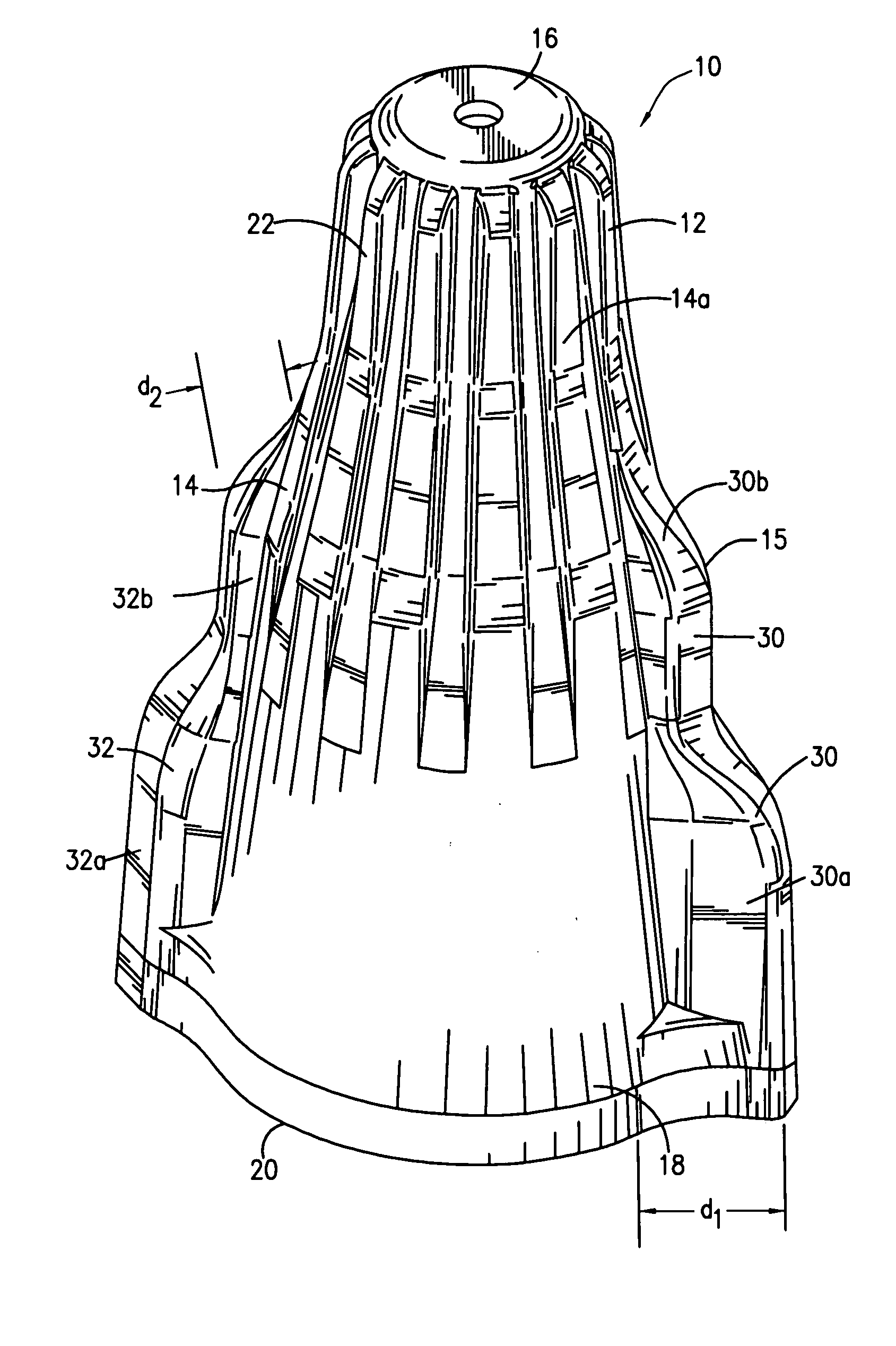
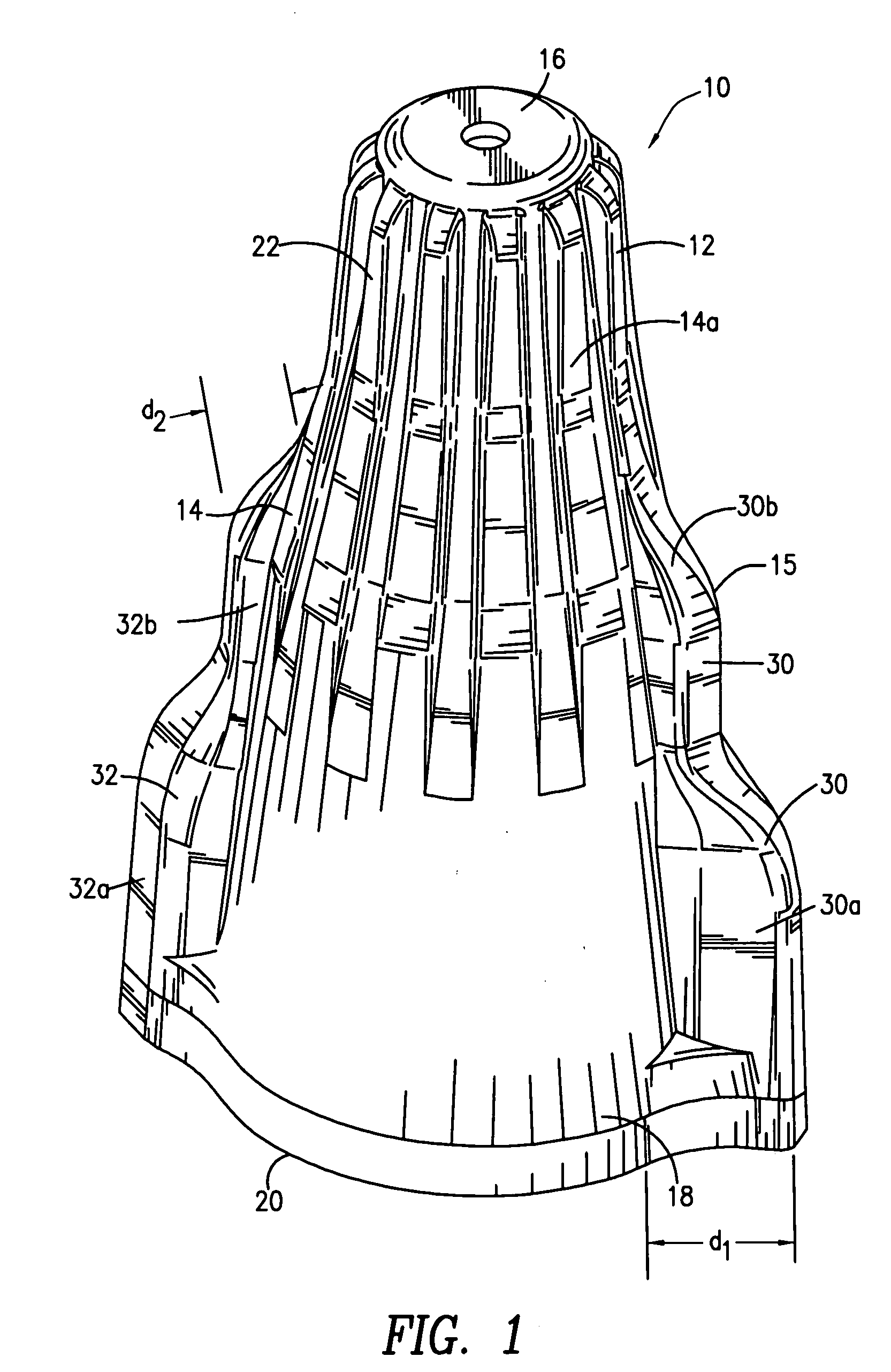
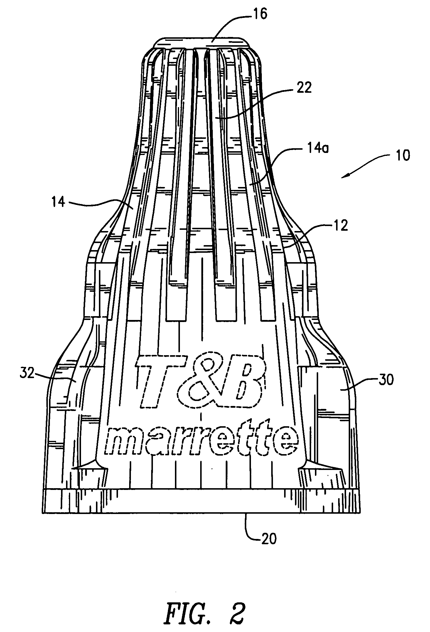
[0015] Referring to FIGS. 1 through 7 of the present invention, a twist-on wire connector 10 of the present invention is shown. Twist-on wire connector 10 is typically a two-piece embodiment including an elongate insulative housing 12 and a conical wire spring (not shown) supported by the housing. As is well-known in the twist-on connector art, the connector 10 may be used to connect two or more insulated or stripped electrical wires together by applying the housing over the ends of the wires. One example of such a conventional twist-on wire connector employing a connector housing and a metallic conical spring is shown in commonly assigned U.S. Pat. No. 5,559,307, the disclosure of which is incorporated by reference herein.

[0016] Housing 12 is an elongate member formed of a suitably insulated molded thermoplastic material. Housing 12 includes a generally frustroconically shaped upper portion 14 tapering towards a closed end 16. A wider lower skirt portion 18 which is nearly cylindr...


PUM


Abstract

A twist-on wire connector including an elongate insulated housing having a closed upper end, an open lower end and a central cavity. The housing includes a pair of diametrically opposed outwardly directed elongate continuous wings. The wings extend from the open end along the longitudinal portion of the housing. The wings have two sections with different dimensions to accommodate manual attachment or attachment by use of a tool such as a socket for applying the connector to the conductors.

Description

CROSS-REFERENCE TO RELATED APPLICATIONS [0001] This application claims priority to U.S. Provisional Application No. 60 / 616,382, filed Oct. 6, 2004.FIELD OF THE INVENTION [0002] The present invention relates generally to a twist-on wire connector used to terminate electrical wires. More particularly, the present invention relates to a twist-on wire connector which may be applied to electrical wires either manually or with the use of a standard socket type tool. BACKGROUND OF THE INVENTION [0003] A well known and common practice is to connect electrical wires using a twist-on or screw-on wire connector. These connectors are used to connect the stripped ends of two or more insulated or non-insulated conductors. Typically, these twist-on wire connectors include a plastic insulated shell and a wire spring supported therein. The wire spring may be conical in shape so that when the connector is placed over the stripped ends of the insulated electrical conductors and twisted thereon, the co...

Claims


Application Information

Patent Timeline
IPC IPC(8): H01R4/00
CPCH01R4/12H01R43/033
Inventor MICHAUD, ALAINPOPOVICI, VIORELFORTIN, PIERRE
Owner THOMAS & BETTS INT INC
Why Eureka
Try Eureka