Contact-less power transfer

a technology of contact-less power transfer and power transfer core, which is applied in the direction of secondary cell servicing/maintenance, transformer/inductance magnetic core, electrochemical generator, etc., can solve the problems of saving the user the cost and inconvenience of regularly having to purchase new cells, the device becomes useless, and the loss of important data stored locally in the devi

Inactive Publication Date: 2005-06-14
PHILIPS IP VENTURES BV
View PDF81 Cites 593 Cited by
  • Summary
  • Abstract
  • Description
  • Claims
  • Application Information

AI Technical Summary

Benefits of technology

[0188]FIG. 9c shows the active area of the primary unit if the coil of FIG. 9a is placed on top of FIG. 9b...

Problems solved by technology

Many of today's portable devices incorporate “secondary” power cells which can be recharged, saving the user the cost and inconvenience of regularly having to purchase new cells.
There are a number of problems associated with conventional means of powering or charging these devices:Both the characteristics of the cells within each device and the means of connecting to them vary considerably from manufacturer to manufacturer, and from device to device.
If users are going away on travel, they will have to bring their collection of chargers if they expect to use their devices during this time.These adaptors and chargers often require users to plug a connector into the device or to place the device into a stand causing inconvenience.
If users fail to plug or place their device into a charger and it runs out of power, the device becomes useless and important data stored locally in the device might even be lost.In addition, most adaptors and chargers have to be plugged into mains sockets and hence if several are used together, they take up space in plug strips and create a messy and confusing tangle of wires.Besides the above problems with conventional methods of recharging devices, there are also practical problems associated with devices having an open electrical contact.
For example, devices cannot be used in wet environments due to the possibility of corroding or shorting out the contacts and also they cannot be used in flammable gaseous environments due to the possibility of creating electrical sparks.
However such chargers still suffer from all other proble...

Method used


Image

  • Contact-less power transfer
  • Contact-less power transfer
  • Contact-less power transfer

Examples


Embodiment Construction

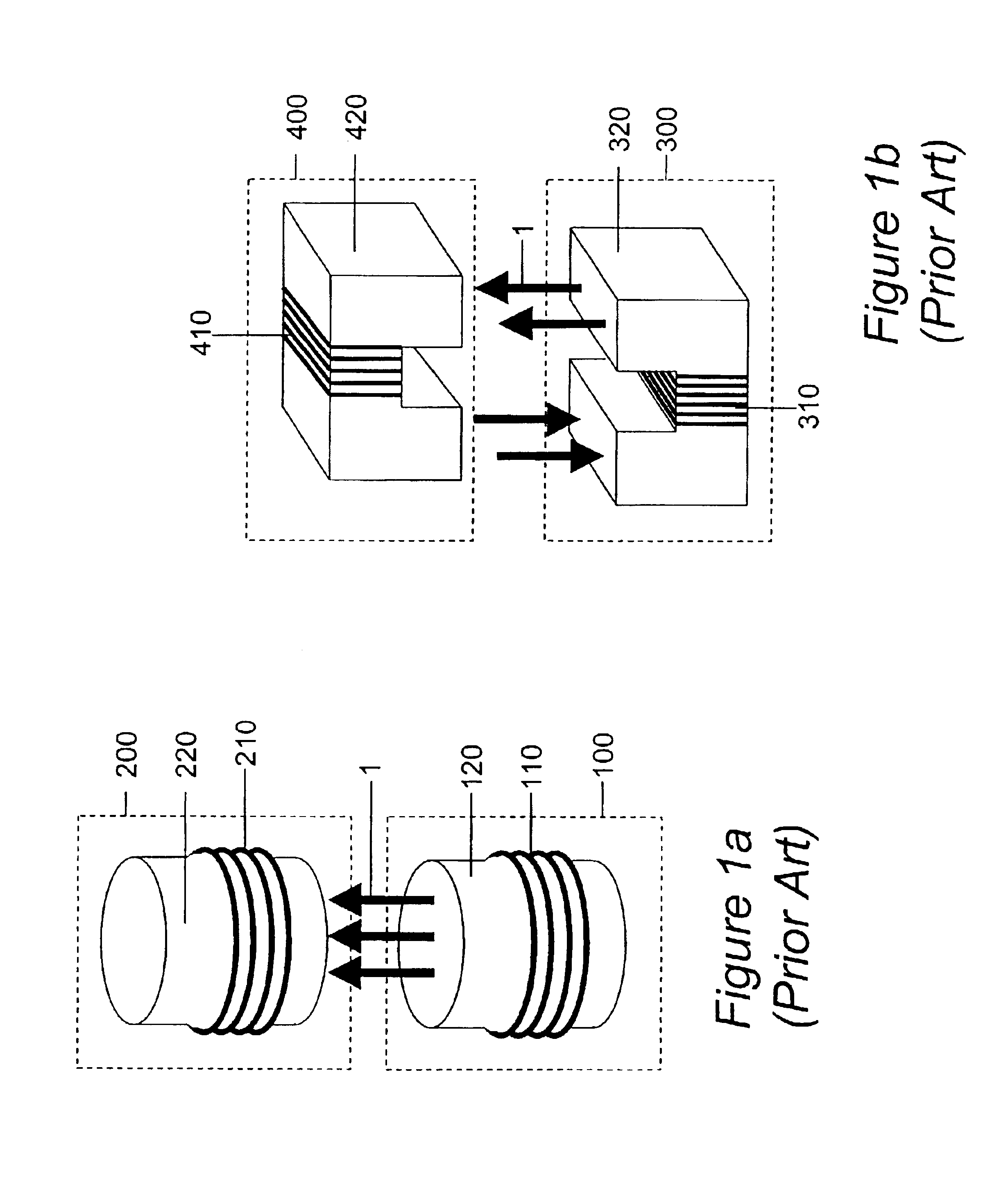
[0193]Referring firstly to FIGS. 1a and 1b, there is shown two examples of prior art contact-less power transfer systems which both require accurate alignment of a primary unit and a secondary device. This embodiment is typically used in toothbrush or mobile phone chargers.

[0194]FIG. 1a shows a primary magnetic unit 100 and a secondary magnetic unit 200. On the primary side, a coil 110 is wound around a magnetic core 120 such as ferrite. Similarly, the secondary side consists of a coil 210 wound around another magnetic core 220. In operation, an alternating current flows in to the primary coil 110 and generates lines of flux 1. When a secondary magnetic unit 200 is placed such that it is axially aligned with the primary magnetic unit 100, the flux 1 will couple from the primary into the secondary, inducing a voltage across the secondary coil 210.

[0195]FIG. 1b shows a split transformer. The primary magnetic unit 300 consists of a U-shaped core 320 with a coil 310 wound around it. Whe...


PUM


Abstract

A system and method for transferring power does not require direct electrical conductive contacts. There is provided a primary unit having a power supply and a substantially laminar surface having at least one conductor that generates an electromagnetic field when a current flows therethrough and having an active area defined within a perimeter of the surface, the at least one conductor being arranged such that electromagnetic field lines generated by the at least one conductor are substantially parallel to the plane of the surface within the active area; and at least one secondary device including at least one conductor that may be wound about a core; wherein the active area has a perimeter large enough to surround the conductor or core of the at least one secondary device in any orientation thereof substantially parallel to the surface of the primary unit in the active area, such that when the at least one secondary device is placed on or in proximity to the active area in a predetermined orientation, the electromagnetic field induces a current in the at least one conductor of the at least one secondary device.

Description

CROSS-REFERENCE TO RELATED APPLICATIONS[0001]The present application claims convention priority from UK patent applications numbers 0210886.8 filed on 13th May 2002, 0213024.3 filed on 7th Jun. 2002 and 0228425.5 filed on 6th Dec. 2002, all of which are incorporated herein by reference.STATEMENT REGARDING FEDERALLY SPONSORED RESEARCH OR DEVELOPMENT[0002]Not applicableREFERENCE TO A “MICROFICHE APPENDIX”[0003]Not applicableBACKGROUND OF THE INVENTION[0004]1. Field of the Invention[0005]This invention relates to a new device and method for transferring power in a contact-less fashion.[0006]2. General Background of the Invention[0007]Many of today's portable devices incorporate “secondary” power cells which can be recharged, saving the user the cost and inconvenience of regularly having to purchase new cells. Example devices include cellular telephones, laptop computers, the Palm 500 series of Personal Digital Assistants, electric shavers and electric toothbrushes. In some of these dev...

Claims


Application Information

Patent Timeline
IPC IPC(8): H01F27/25H01F3/00H01F3/02H01F38/14H01F41/02H01F27/28H01F5/00H02J7/02H01F27/245H02J5/00
CPCH01F3/02H01F5/003H01F27/25H02J7/025H01F38/14H01F41/0226H01F41/0233H01F27/2804H01F27/245H02J5/005H02J50/402H02J50/70H02J50/12
Inventor CHENG, LILY KA LAIHAY, JAMES WESTWOODBEART, PILGRIM GILES WILLIAM
Owner PHILIPS IP VENTURES BV
Why Eureka
Try Eureka