Planar resonator for wireless power transfer

a wireless power transfer and planar resonance technology, applied in waveguide devices, inductances, transportation and packaging, etc., can solve the problem of lack of contactless power transfer systems in the prior art, and achieve the effect of facilitating the arrangement of woven wires and facilitating the use of wearable electronics

Inactive Publication Date: 2005-11-01
KONINKLIJKE PHILIPS ELECTRONICS NV
View PDF20 Cites 610 Cited by
  • Summary
  • Abstract
  • Description
  • Claims
  • Application Information

AI Technical Summary

Benefits of technology

[0011]An advantage of the present invention is that it facilitates the use of wearable electronics. For example, flex circuits may be used so as to cause the surface of the coils to be flexible. In addition to the flexibility, the coils may be formed in any arbitrary shape to facilitate woven wire arranged in a fabric, or pads with embedded conductors that can be attached to clothes. In this way, for example, one could charge a radio, cellphone, and/or computer (just to name a few of the many wearable items) by bringing the device in close proximity to the fabric. Thus, implementation of the invention with wearable electronics could provide an interface between the wearable device(s) and external power sources. Digital or analog signals may also be transmitted across such interfaces to, for instance, up- or download digital information.
[0012]In another aspect of the invention, the IOET of the planar power resonator may have a thin and/or relatively flat top coil surface. In a wireless application, the IOET may be comprised of, for instance, (i) a non-conductive/dielectric film (for isolation) on the bottom of the top spiral(s), (ii) air; and (iii) a non-conductive/dielectric film (for isolation) on the top of the bottom spiral(s). The coils may be arranged in an upper and lower configuration substantially axially aligned. In addition, there can be an emulsifier at the bottom portion of an upper coil, with an air gap between the emulsifier and the top portion of the lower coil.
[0013]The spiral-

Problems solved by technology

The prior art lacks a system for contactless power transfer that includes capacitive-coupl

Method used


Image

  • Planar resonator for wireless power transfer
  • Planar resonator for wireless power transfer
  • Planar resonator for wireless power transfer

Examples


Embodiment Construction

[0036]The following description is provided for purposes of illustration, and not for limitation. There are many different configurations that are well within the spirit of the invention, and the scope of the appended claims.

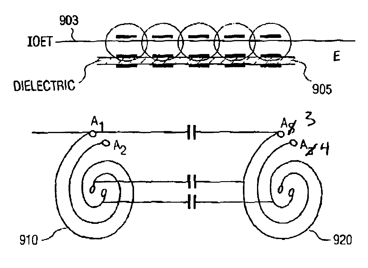
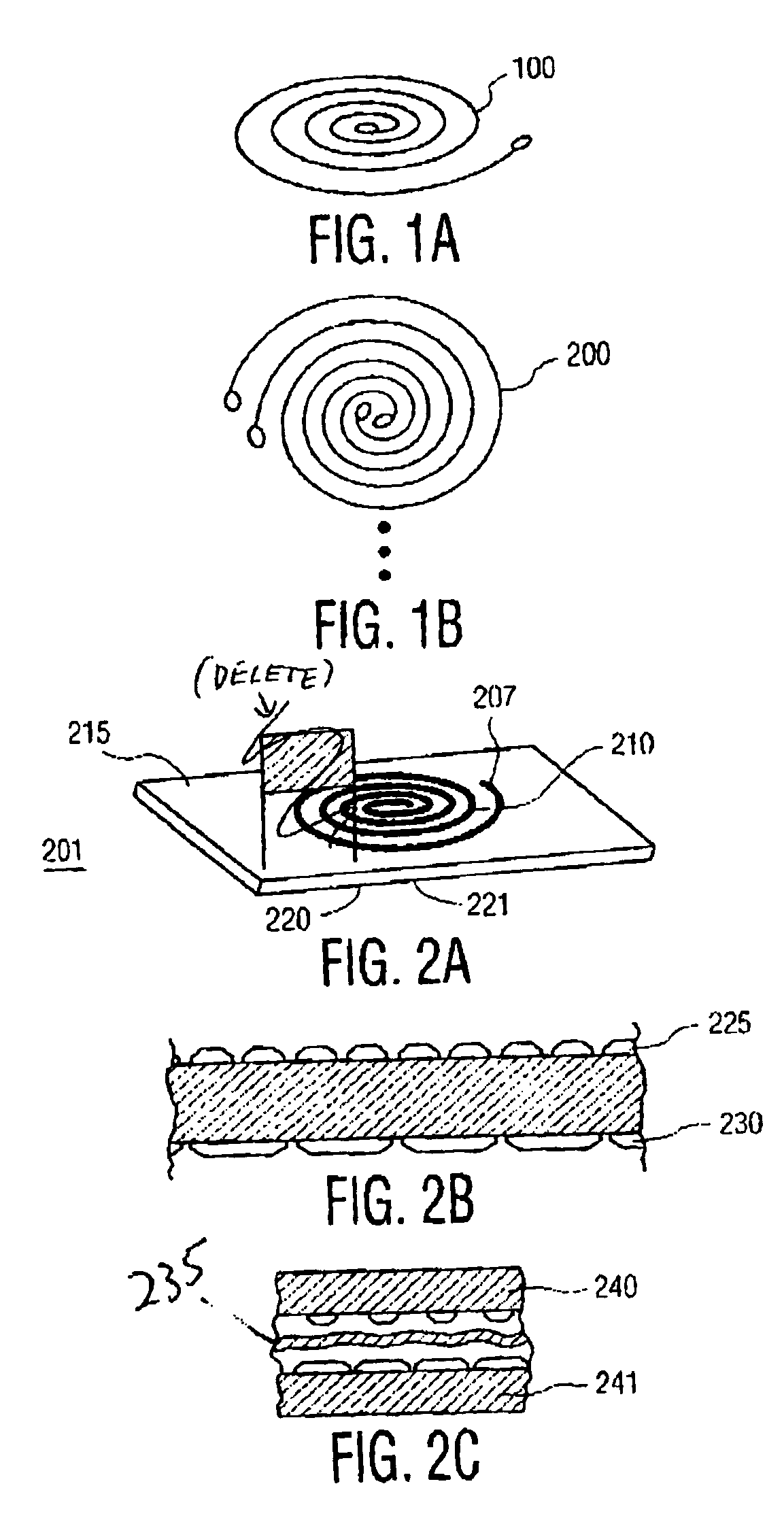
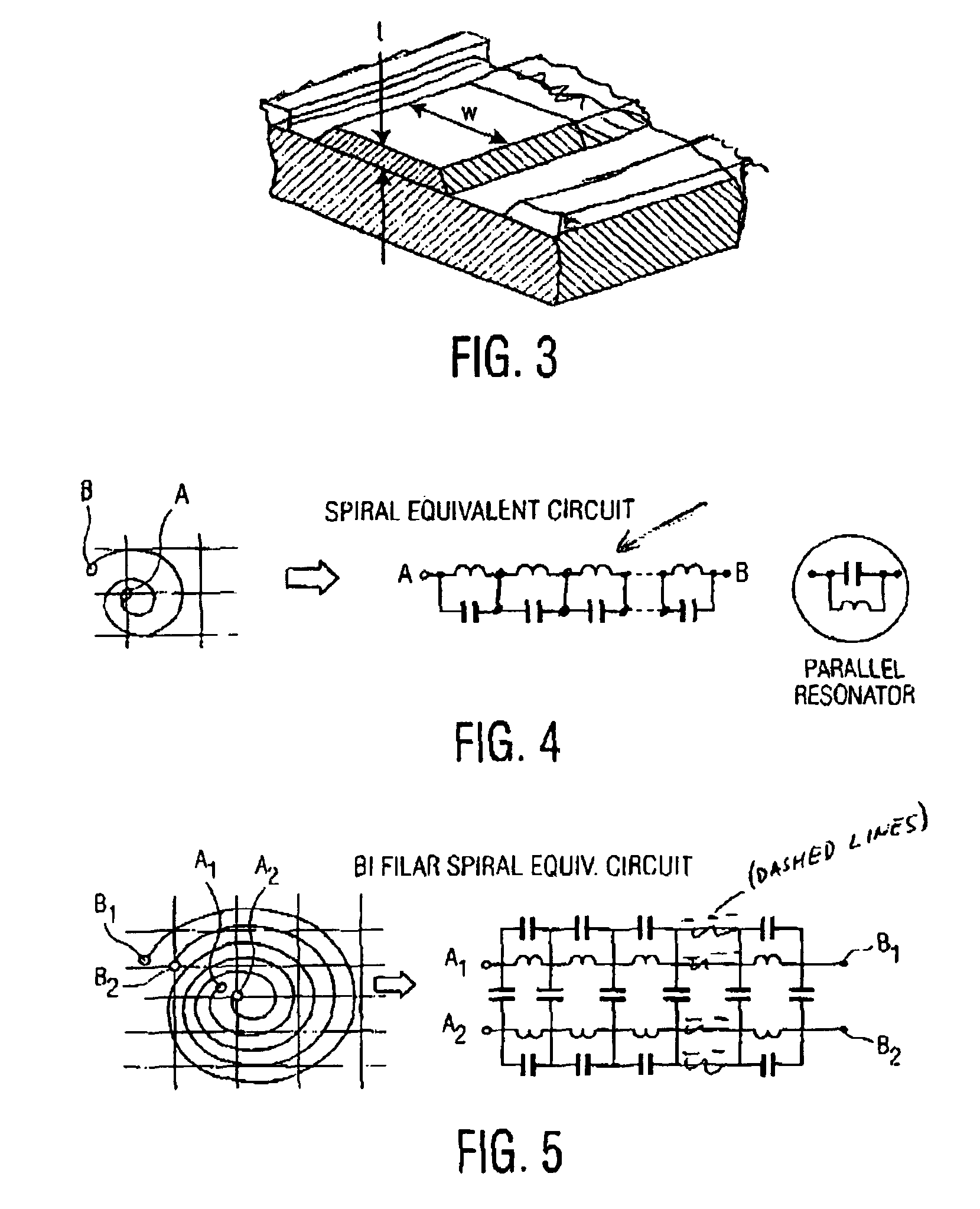
[0037]FIGS. 1A-1B illustrate variations of planar integrated resonators according to an aspect of the present invention. An integrated resonator is obtained by storing electric energy in a part of the time-energy function of a structure (geometry) that also stores magnetic energy in a part of the same function.

[0038]FIG. 1A illustrates an example of a basic spiral 100, whereas FIG. 1B illustrates a bi-filar spiral 200. Of course, it should be understood by persons of ordinary skill in the art that the present invention is not limited to spirals and bi-filar spirals, and may use any number of spiral wrappings (multi-filar) according to need. As shown in FIG. 2A, the planar 200 has a spiral 210 wound on a top side of the interface-of-energy-transfer (IOET) 215, an...


PUM


Abstract

A planar resonator and method of manufacture provides contactless power transfer using at least two electrically isolated axis aligned conductive across the transfer interface in a coupled inductor or transformer configuration. Signal or power transfer is then accomplished by coupling of magnetic flux. The coupling of electric flux is also accomplished across a same interface and driven with the same conductive spiral-wound conductors. An interface of energy transfer(IOET) has a first spiral-shaped conductor arranged on the top surface of said IOET; a second spiral-shaped conductor arranged on the bottom surface of said IOET, has a vertical axis aligned with the first spiral-shaped conductor. The IOET and the first and second spiral-shaped conductors have a predetermined self-resonant frequency. The planar power resonator stores electric energy in the IOET, and at predetermined frequencies, the arrangement of the first and second spiral-shaped conductors and the IOET permits transfers of magnetic flux and electrical energy between the first and second spirals across the IOET. The resonator facilitates contactless battery charging in devices such as cellphones and wearable electronics where the resonator can be woven into fabric or attached to a person's clothes.

Description

FIELD OF THE INVENTION[0001]The present invention is related to contactless power transfer systems. More particularly, the present invention is related to a planar resonator for wireless power transfer in a contactless power transfer system.BACKGROUND AND SUMMARY OF THE INVENTION[0002]Contactless power transfer has been used in applications such as the non-intrusive charging of pacemaker batteries, the charging of hybrid vehicle batteries, etc. In such applications, inductive coupling is used exclusively so that a current is induced from a power station to a load. In such systems, the power transfer is exclusively accomplished by means of coupling magnetic flux of the power station and the load.[0003]For example, road systems that would encourage the use of electric vehicles have been studied by states such as California. In such a system, inductively coupled flat coils are embedded in the roadway, or cables that are embedded in the roadway are energized, so that an induction coil o...

Claims


Application Information

Patent Timeline
IPC IPC(8): H01F38/14H01F17/00H02J7/02H01P7/00
CPCH01F17/0006H01F38/14H02J7/025H01P7/00H03H7/01H02J50/12
Inventor ODENDAAL, WILLEM G.LI, YUSBAN
Owner KONINKLIJKE PHILIPS ELECTRONICS NV
Why Eureka
Try Eureka