Braking and drive force control apparatus for a vehicle

a technology of braking and driving force control and control apparatus, which is applied in the direction of non-deflectable wheel steering, process and machine control, electric devices, etc., can solve the problems of inadequate consideration of upward and downward vibration of the vehicle body, poor ride comfort, and insufficient consideration of the variations of the ground contact load of the wheels, so as to achieve the effect of running stability, maintaining ride comfort, and suppressing the variation of the ground contact load

Active Publication Date: 2006-04-13
TOYOTA JIDOSHA KK
View PDF12 Cites 11 Cited by
  • Summary
  • Abstract
  • Description
  • Claims
  • Application Information

AI Technical Summary

Benefits of technology

[0007] The present invention was made in order to cope with the above-described problems, and its object is to provide a braking and drive force control apparatus for a vehicle which does not require the suspension to be set on the hard side and thus can maintain ride comfort and which can control the drive force of wheels in accordance with upwards and downwards vibration of vehicle parts such as the vehicle body or the wheels, in order to suppress bouncing of a vehicle body to thereby achieve running stability of the vehicle, and to suppress variations in the ground contact load of the wheels to thereby achieve running stability of the vehicle.
[0010] If a difference in the drive forces of the front and rear wheels is created in accordance with the upwards and downwards vibration of the vehicle body which is sensed by the vehicle body upwards and downwards vibration sensing means, force can be applied in the direction suppressing upwards and downwards vibration of the vehicle body. Namely, the wheels are suspended on the vehicle body through the suspension apparatus, so if a difference is produced in the drive forces of the front and rear wheels, the forces in the fore and aft direction of the vehicle which are generated by the front and rear wheels can be applied to the vehicle body through the suspension. As a result, the suspension is not set on the hard side, and thus ride comfort can be maintained. Further, without setting the suspension on the hard side, bouncing of the vehicle body can be suppressed, and the running stability of the vehicle can be achieved.
[0012] If the drive force of the wheels is changed in accordance with the upwards and downwards vibration of the wheels which is sensed by the wheel upwards and downwards vibration sensing means, a force in the direction permitting upwards and downwards vibration of the wheels can be applied. Namely, the wheels are suspended on the vehicle body by the suspension, so a component of the force in the fore and aft direction of the vehicle which is generated at the wheels can be applied to the suspension, and other components of force in the fore and aft direction can be applied to the wheels. The wheels can be made to follow the ground surface and move upwards and downwards by the force applied to the wheels. As a result, the suspension is not set on the hard side, and thus ride comfort can be maintained. Further, without setting the suspension on the hard side, variation of the ground contact load can be suppressed, and running stability of the vehicle can be achieved.

Problems solved by technology

However, the above-described prior art does not give adequate consideration to upwards and downwards vibration of the vehicle body, i.e., to bouncing of the vehicle body.
However, suppressing bouncing in this manner results in the problem that the ride comfort becomes poor.
In addition, in the above-described prior art, adequate consideration is not given to variations in the ground contact load of the wheels.
In the same manner as described above, variation in the ground contact load of the wheels is suppressed by setting the suspension on the hard side, but again this results in the problem that the ride comfort worsens.

Method used


Image

  • Braking and drive force control apparatus for a vehicle
  • Braking and drive force control apparatus for a vehicle
  • Braking and drive force control apparatus for a vehicle

Examples


first embodiment

a. First Embodiment

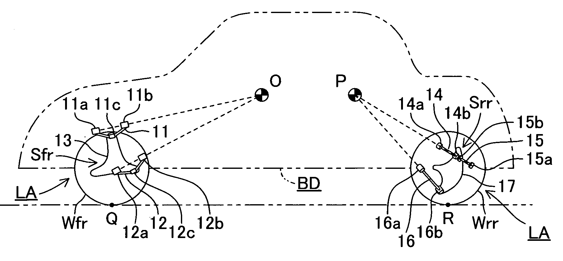
[0023] Below, a braking and drive force control apparatus according to a first embodiment of the present invention will be described while referring to the drawings. FIG. 1 is a schematic side view showing the righthand portion of a vehicle.

[0024] The left and right, front and rear wheels Wfl, Wfr, Wrl, and Wrr of the vehicle are suspended on a vehicle body BD by suspensions Sfl, Sfr, Srl, and Srr (see FIG. 2). The suspensions Sfl, Sfr, Srl and Srr have the same structure on the left and right sides of the vehicle, so only the suspensions Sfr and Srr positioned on the right side of the vehicle will be explained in detail, and a detailed explanation of the suspensions Sfl and Srl positioned on the left side of the vehicle will be omitted.

[0025] The front suspension Sfr includes an upper arm 11 and a lower arm 12. The upper arm 11 is mounted on the vehicle body BD at its inner ends 11a and 11b for rotation about an axis extending in roughly the fore and aft direct...

second embodiment

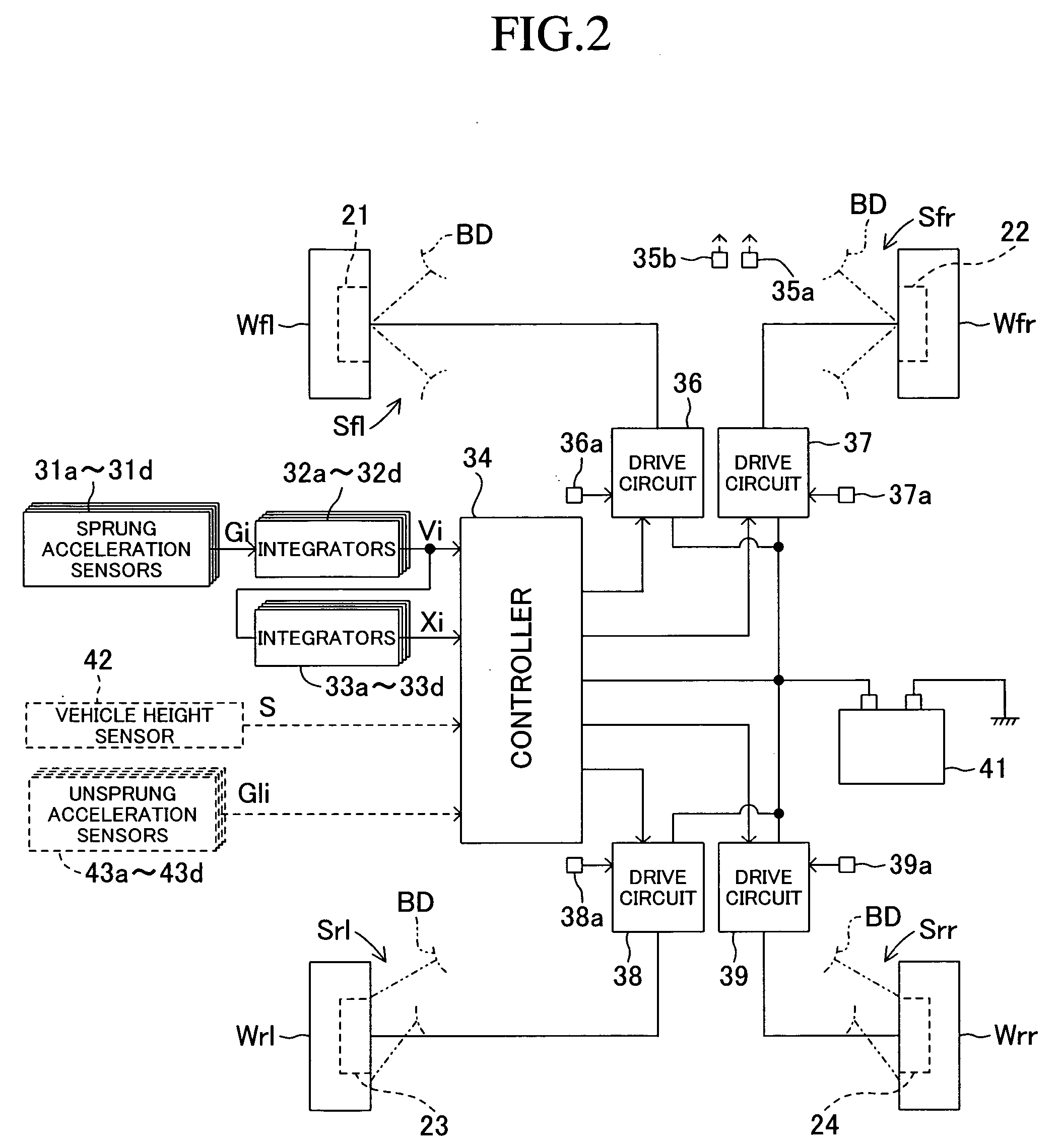
[0046] Next, a second embodiment of the present invention will be described. As shown by dashed lines in FIG. 2, a braking and drive force control apparatus for a vehicle according to this second embodiment has unsprung acceleration sensors 43a-43d instead of sprung acceleration sensors 31a-31d. The unsprung acceleration sensors 43a-43d are respectively mounted on the lower arms 12, 12, 16, and 16 of the suspensions for the left and right, front and rear wheels Wfl, Wfr, Wrl, and Wrr. They respectively sense the unsprung acceleration Gli (i=1−4) of the left and right, front and rear wheels Wfl, Wfr, Wrl, and Wrr in the upwards and downwards direction with respect to absolute space. A positive value for the unsprung acceleration Gli (i=1−4) indicates upwards acceleration, and a negative value indicates downwards acceleration. The unsprung acceleration sensors 43a-43d function as a wheel upwards and downwards vibration sensing means. A controller 34 according to this second embodiment...


PUM


Abstract

A braking and drive force control apparatus for a vehicle whose wheels are separately driven by electric motors. A controller calculates a drive force or a braking force to be applied to each wheel in accordance with the average sprung displacement and average sprung velocity of the vehicle body which are calculated based on sensed sprung acceleration. By adding the calculated drive force or braking force to the drive force at the time of running, at the time of bouncing of the vehicle body, a downwards force can be generated in the vehicle body which is rising, and an upwards force can be generated in the vehicle body which is descending. By applying an upwards or downwards force to each wheel so as to permit upwards and downwards vibration of the wheels, variations in the ground contact load can be suppressed.

Description

BACKGROUND OF THE INVENTION [0001] 1. Technical Field [0002] This invention relates to a braking and drive force control apparatus for a vehicle which can perform variable control of the braking and drive force applied to the wheels of the vehicle. [0003] 2. Related Art [0004] From in the past, as described in Japanese Patent Application Laid-Open (kokai) No. H 10-210604, for example, an in-wheel motor type vehicle in which a motor is incorporated into each drive wheel is known. The drive force of each drive wheel is individually controlled so that the yaw rate response of the vehicle body to the steering angle sensed by a steering angle sensor matches a target response, and the yawing performance is improved by reflecting rotational movement, sideways movement, slip, and the like of the vehicle body in drive control of each drive wheel. [0005] However, the above-described prior art does not give adequate consideration to upwards and downwards vibration of the vehicle body, i.e., to...

Claims


Application Information

Patent Timeline
Patent Type & Authority Applications(United States)
IPC IPC(8): B60G17/005B60K17/348B60L15/00B60L15/20B60T8/17B60W30/00B60W30/02
CPCB60L7/00Y02T10/648B60G2200/14B60G2204/182B60G2300/50B60G2400/102B60G2400/206B60G2400/252B60G2800/014B60K6/52B60L15/20B60L15/2009B60W10/08B60W30/20B60L2220/46B60L2240/463B60W2520/16B60W2710/083B60L2240/46B60G17/0195Y02T10/7275Y02T10/6265B60G3/20Y02T10/62Y02T10/64Y02T10/72
Inventor SUGIYAMA, MIZUHO
Owner TOYOTA JIDOSHA KK
Why Eureka
Try Eureka