Wheel-immobilizing device

a technology of immobilizing device and wheel, which is applied in the direction of anti-theft device, anti-theft cycle device, cycle stand, etc., can solve the problems of not being able to easily lift, difficult or impossible to lift, and the clamshell-type device that requires the wheel to be lifted from the ground in order to be installed is not suitable for immobilizing very heavy carts or cabinets, and achieves the effect of hammering the rolling movement of the cabin

Active Publication Date: 2006-04-20
D & D SECURITY RESOURCES
View PDF27 Cites 7 Cited by
  • Summary
  • Abstract
  • Description
  • Claims
  • Application Information

AI Technical Summary

Benefits of technology

[0006] The present invention provides a wheel-immobilizing device that does not require holes or indentations in the wheel in order for the device to be secured around the wheel or caster being immobilized. Additionally, a wheel-immobilizing device according to the invention is configured such that it may be placed on the ground in front of a cabinet, and the cabinet simply rolled into position with one of its ca

Problems solved by technology

The wheels or casters on many carts and cabinets, however, have no holes or indentations; therefore, a Denver boot-style device can not be used to immobilize them.
If the cabinet to be immobilized is heavy, however, i

Method used


Image

  • Wheel-immobilizing device
  • Wheel-immobilizing device
  • Wheel-immobilizing device

Examples


Embodiment Construction

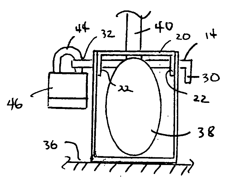
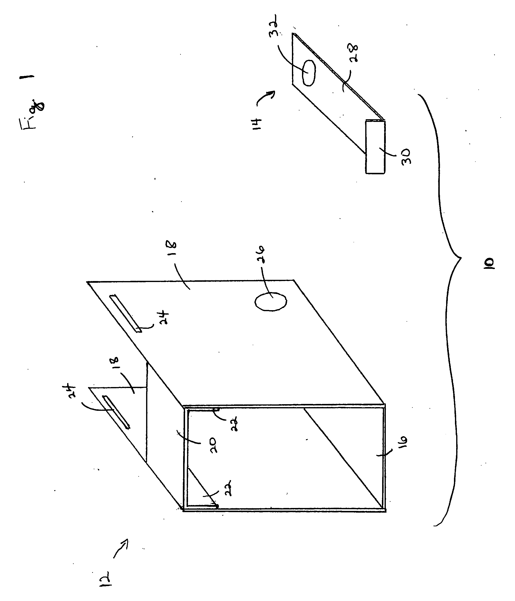
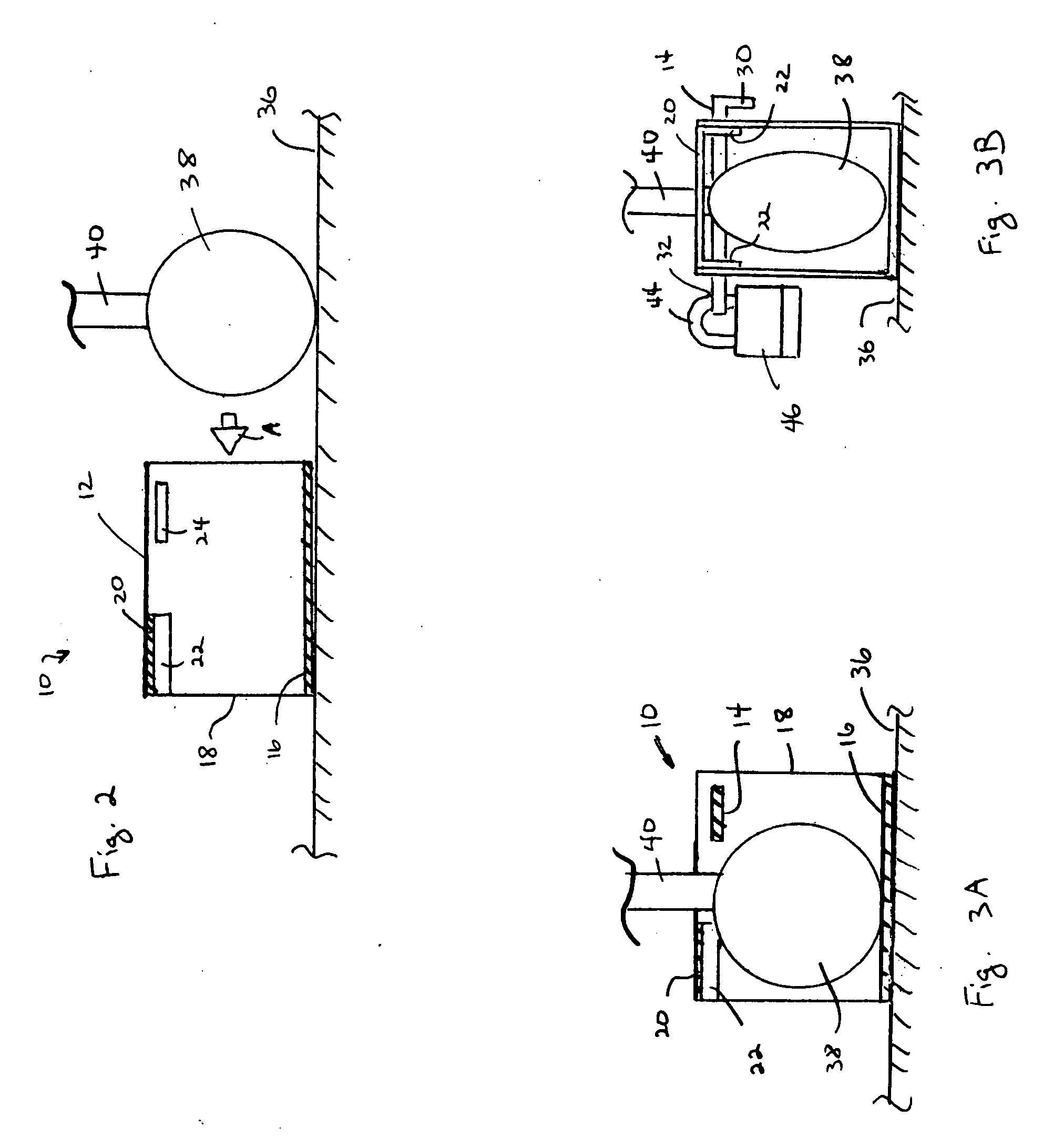
[0024] A first embodiment 10 of a wheel-immobilizing device according to the invention is illustrated in FIGS. 1, 2, 3A, and 3B. The device 10 includes a base unit 12 and a separate, removable cross member or locking bar 14.

[0025] The base unit 12 has a base member 16 and a pair of side walls 18 extending upwardly from the base member 16, giving the base unit 12 a generally U-shaped trough configuration. A fixed cross member 20 extends between the side walls 18 and is securely attached to the two side walls 18. As illustrated, the cross member 20 may be formed with a general bracket configuration, with the flange portions 22 of the bracket being spot-welded to the inner-facing surfaces of the side walls 18. The base unit 12 and the cross member 20 may be stamped from 16 gauge sheet metal (steel), then bent or roll-formed into their respective configurations before being welded together. A pair of slots 24 are formed through the side walls 18 and are located opposite to each other. ...


PUM


Abstract

The present invention provides a wheel-immobilizing device that does not require holes or indentations in the wheel in order for the device to be secured around the wheel or caster being immobilized. Additionally, a wheel-immobilizing device according to the invention is configured such that it may be placed on the ground in front of a cabinet, and the cabinet simply rolled into position with one of its casters between side walls of the device. The wheel-immobilizing device is then secured around the caster by passing a cross member or, in some embodiments, two cross members through the side walls on either side of the caster stem and then securing the cross member or members in position, thereby locking the wheel-immobilizing device to the caster of the cabinet and hampering rolling movement of the cabinet.

Description

BACKGROUND AND FIELD OF THE INVENTION [0001] 1. Field of the Invention [0002] The invention relates to wheel-immobilizing devices. More particularly, the invention relates to a wheel-immobilizing device that is particularly suited to inhibit rolling movement of a wheeled cart or cabinet or other caster-supported item. [0003] 2. Background of the Invention [0004] There are various instances in which it is desirable to prevent a wheeled item from moving. For example, it is known to immobilize cars for which violations have not been paid using what is referred to as a “Denver boot.” A Denver boot has a clam-shell-type body and a blocking arm that protrudes from the body. The body is clamped around the wheel of a car and locked in place, and the blocking arm prevents the wheel from rolling by striking the ground or the underside of the car if moving the car is attempted. The Denver boot utilizes holes or indentations in the wheel in order for it to be secured to the wheel. The wheels or...

Claims


Application Information

Patent Timeline
IPC IPC(8): B60R25/00B62H5/14
CPCB60R25/093B62H3/04Y10T70/5836Y10T70/5841
Inventor SMITH, DONNA L.SMITH, DEAN H.
Owner D & D SECURITY RESOURCES
Why Eureka
Try Eureka