
Cooking appliance with stationary grate and moveable heat source

Inactive Publication Date: 2006-04-20
LUNDH ANDERS P +2
View PDF10 Cites 64 Cited by
  • Summary
  • Abstract
  • Description
  • Claims
  • Application Information

AI Technical Summary

Benefits of technology

[0008] The top unit may be rotatably coupled to the base frame for rotational displacement with respect thereto between the closed position and the open position, such as by 45°, or advantageously by approximately 180°. A support may be attached to the top unit and operative to support the top unit in a generally horizontal position in the open position. The heating unit may compr

Problems solved by technology

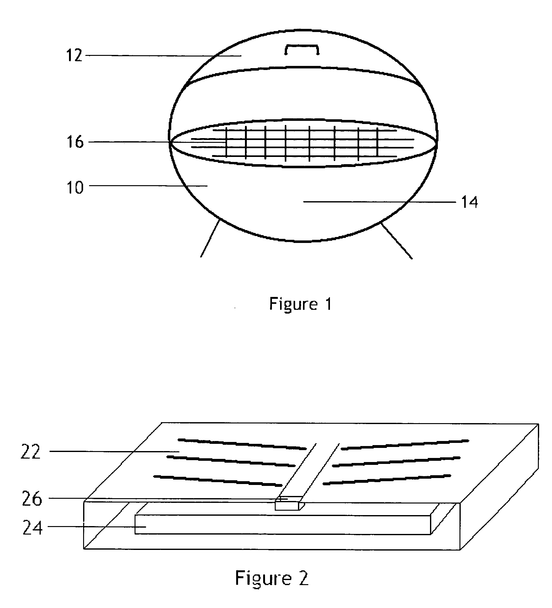
When the oil and other fluids fall on the heating element 14, the oils and fluids burn and smoke is created, which makes the cooking device unsuitable for indoor usage.
However, cooking the food directly on the heated cookware plate 22 results in some of the oils / fluids to be cooked with the food thus giving the food a burnt taste.
The food that sticks to the heating element or the additional cookware plate are very hard to remove because of its burnt condition.
This will cause the cooking device to, over time, accumulate burnt grease, oil or food residue resulting in the user eventually needing to replace the heating element and / or additional cookware plates.
Removing the food from the oven can be hazardous and cause injuries and discomfort.

Method used


Image

  • Cooking appliance with stationary grate and moveable heat source
  • Cooking appliance with stationary grate and moveable heat source
  • Cooking appliance with stationary grate and moveable heat source

Examples


Embodiment Construction

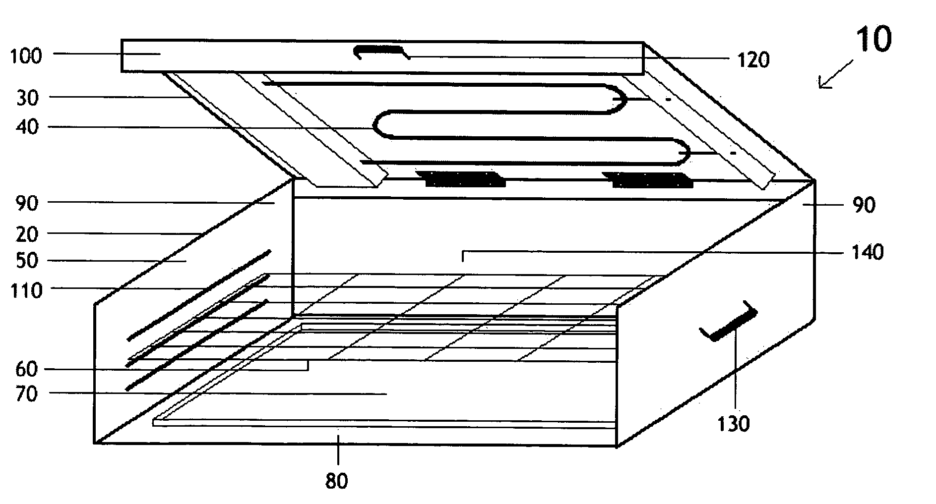
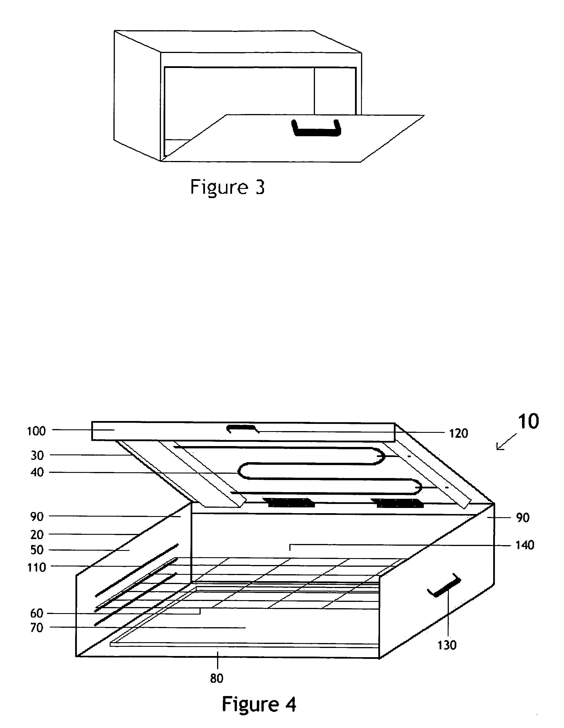
[0016] One embodiment of a cooking device according to the present invention is shown in FIG. 4, and generally indicated at 10. The cooking device 10 includes a housing 20, a grate 60, and a collection pan 70. The housing 20 includes a lower base frame 50 and a lid assembly 30. The base frame 50, as shown, assumes a generally U-shaped profile, with a bottom 80 and respective sidewalls 90, and should be made of a suitable heat resistant material such as stainless steel or aluminum. The lid assembly 30 includes a lid or cover 100 with a heating element 40 attached thereto. The heating element 40 may advantageously be in the form of W-shaped electric resistance element of 1700 watts that can heat to at least 1000° F. Alternatively, the heating element 40 may take other forms, such as a gas heat source known in the art. While not required in all embodiments, the lid assembly 30 may advantageously be pivotally mounted to the base frame 50 via one or more hinges or other means for allowin...


PUM


Abstract

A cooking device having a base frame having sidewalls and a floor that at least partially define a cooking cavity; a lid assembly disposed above the base frame and comprising a cover and a heating unit; a grate disposed in the cooking cavity; a collecting pan disposed beneath the grate for collecting drippings from food being cooked; the top unit being displaceable relative to the base frame between a closed position and an open position, wherein, in the open position, the heating unit is disposed out of alignment with the grate and the top unit is disposed so as to allow access to the grate from above. The collecting pan may be disposed so as to remain below 180° F. after 20 minutes of cooking with the top unit in the closed position and the heating unit operating at a maximum setting.

Description

BACKGROUND OF THE INVENTION [0001] The present invention relates to a cooking appliance, more particularly to a cooking appliance that is suitable for grilling and baking food. [0002] As shown in FIG. 1, a conventional cooking grill includes a base unit 10 and a cover unit 12. The base unit 10 consists of a heat resistant material and houses the heating element 14 (e.g., burning coal). The heating element provides heat to the cookware grate 16. The cover unit 12 is made out of a heat resistant material. It is mounted so that it can be closed with the base unit 10 forming an enclosed chamber. [0003] When placing food on the cookware grate 16 and providing heat from the heating element, oil and other fluids tend to drip on to the heating element 14. When the oil and other fluids fall on the heating element 14, the oils and fluids burn and smoke is created, which makes the cooking device unsuitable for indoor usage. [0004] As shown in FIG. 2, an additional cookware plate 22 can be moun...

Claims


Application Information

Patent Timeline
IPC IPC(8): F24C15/00
CPCA47J37/0623A47J37/0629A47J37/0709
Inventor LUNDH, ANDERS P.DARAI, PIROOZALAYAN, HUSSEIN A.
Owner LUNDH ANDERS P
Learn More