Fines removal apparatus and methods/systems regarding same

a technology of fines and equipment, applied in the direction of chemistry apparatus and processes, solid separation, sorting, etc., can solve the problems of uneconomical separation of fines from feed mixtures, high operating costs, and high capital costs of vibrating screen equipmen

Active Publication Date: 2006-04-20
RGT UNIV OF MINNESOTA
View PDF61 Cites 11 Cited by
  • Summary
  • Abstract
  • Description
  • Claims
  • Application Information

AI Technical Summary

Benefits of technology

[0005] The systems, apparatus, and / or methods according to the present invention overcome one or more of the problems described herein relating to other previously used or described separation systems and methods. One embodiment of a fines removal apparatus according to the present invention for use in separation of objects from a feed mixture (e.g., a feed mixture that includes the objects and fines, such as rounded iron bearing pellets along with pellet dust and pellet chips) includes an endless belt. At least a portion of the endless belt is movable up an incline relative to horizontal (i.e., the incline is at an angle relative to horizontal that is greater than an angle of repose associated with the objects but less than an angle of repose associated with the fines). The endless belt includes an endless base section having a predetermined length and first and second sidewalls extending from the endless base section. The endless base section and the first and second sidewalls define a channel of the endless belt configured to receive the feed mixture therein. The endless belt further includes a plurality of obstruction elements, wherein each obstruction element includes at least one surface portion that extends between a first position and a second position of the endless base section such that the at least one surface portion impedes a flow of fines down the incline when feed mixture is provided in the channel and as the portion of the endless belt is moved up the incline. The fines removal apparatus further includes a drive apparatus coupled to the endless belt to move the portion of the endless belt up the incline.

Problems solved by technology

However, such vibrating screen equipment is very capital cost and operating cost intensive (e.g., maintenance costs associated with such equipment) which makes the separation of fines from a feed mixture (e.g., a feed mixture including such pellets, dust, pellet chips, etc.) uneconomical.
Further, such vibrating screen equipment may cause physical breakage and abrasion to the whole pellets being separated from the fines.

Method used


Image

  • Fines removal apparatus and methods/systems regarding same
  • Fines removal apparatus and methods/systems regarding same
  • Fines removal apparatus and methods/systems regarding same

Examples


Embodiment Construction

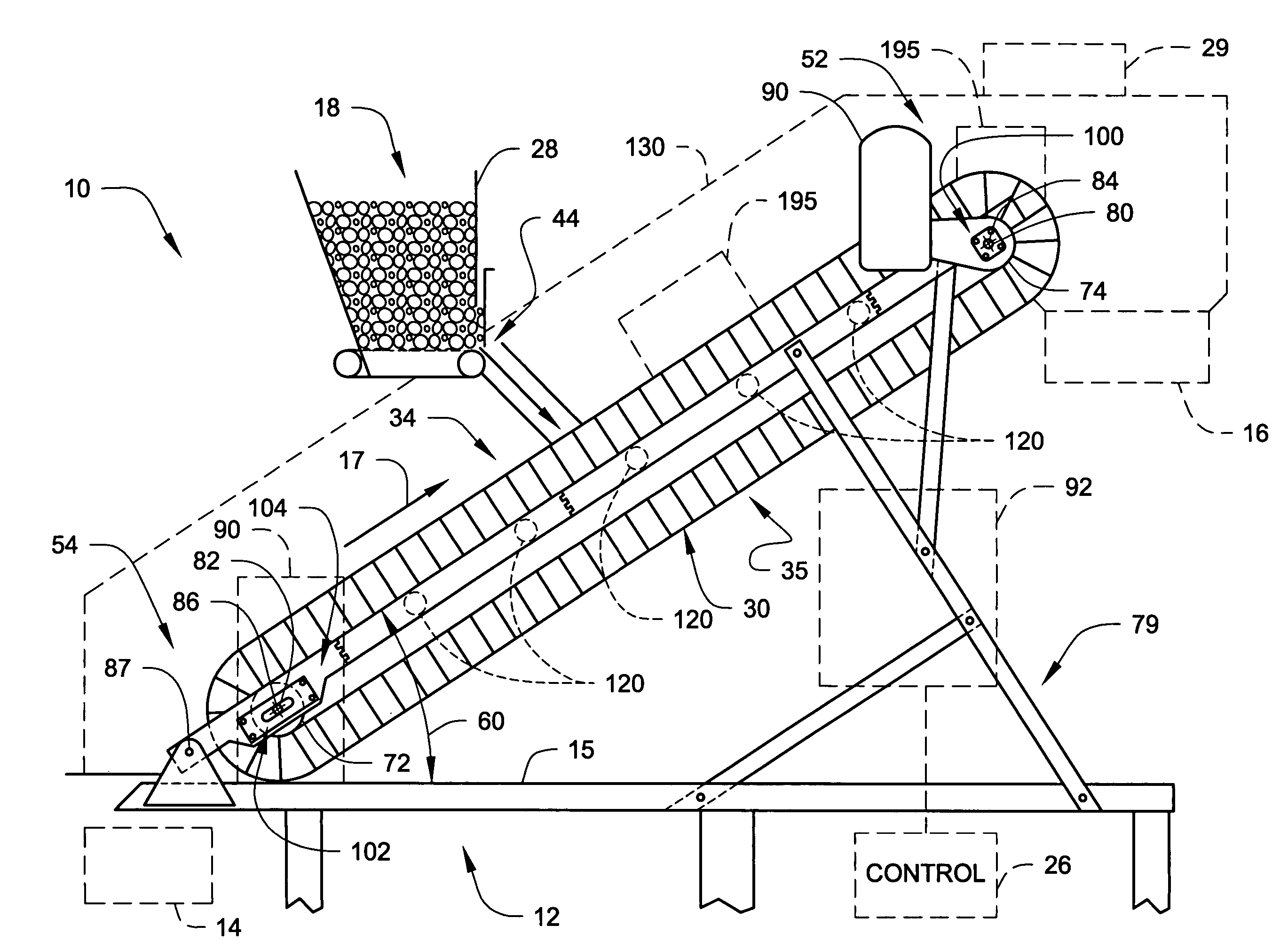
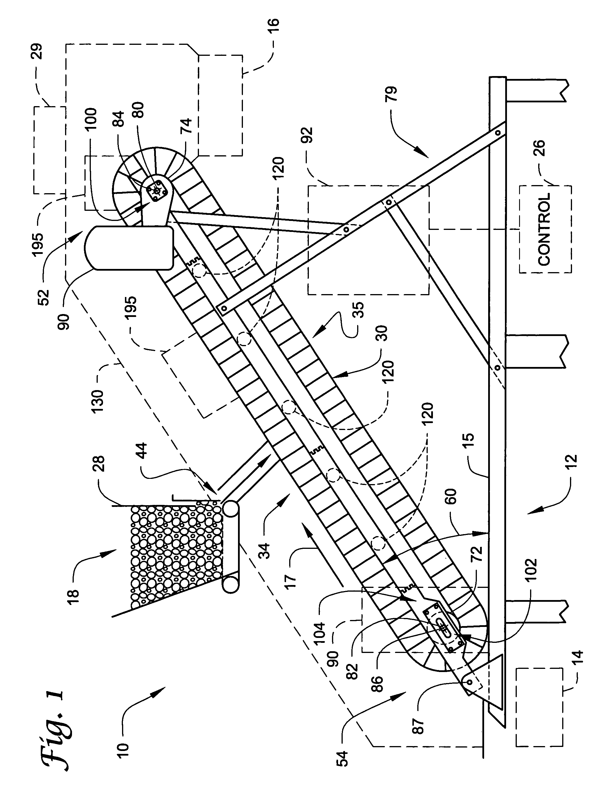
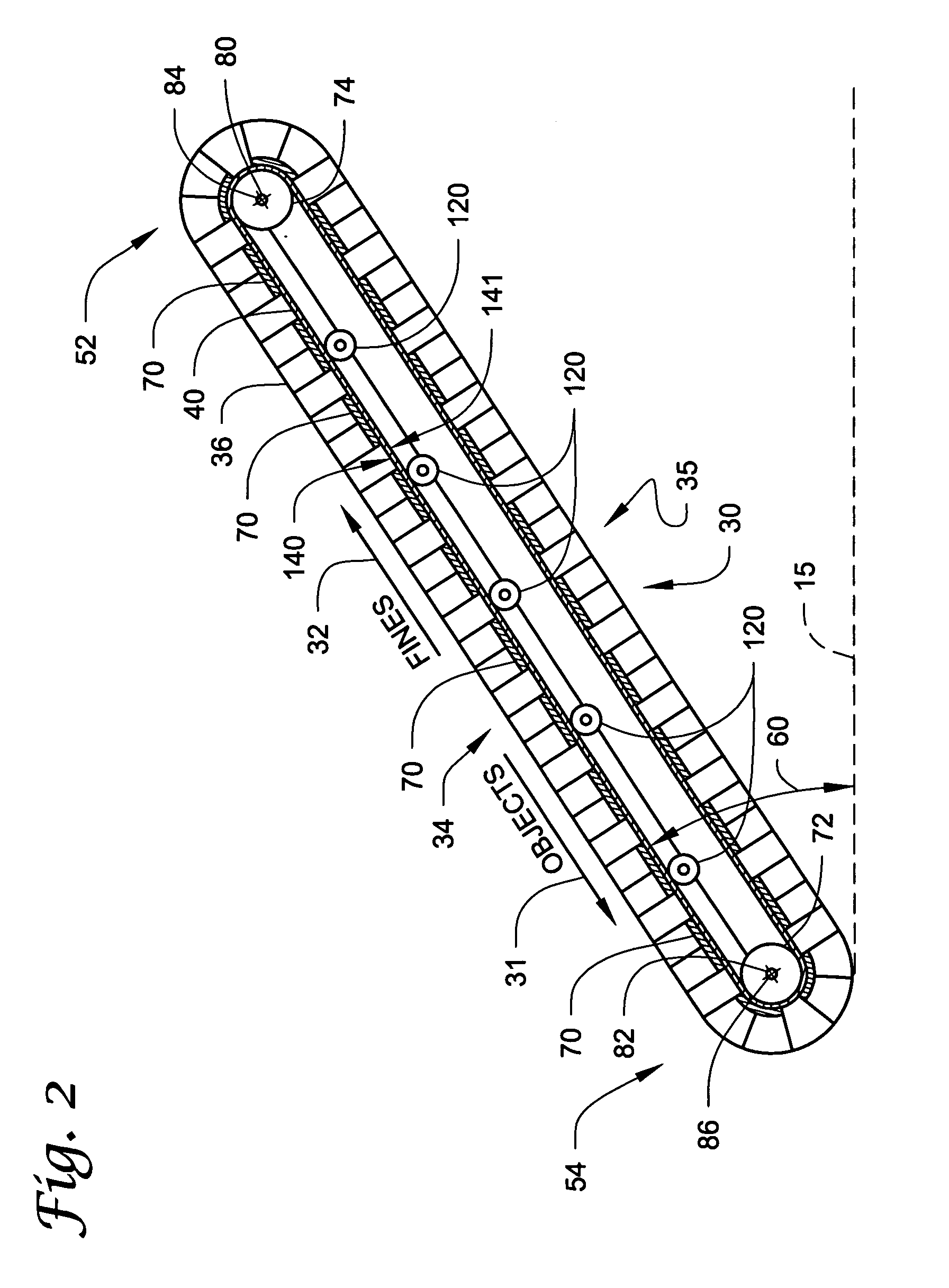
[0029] The present invention shall generally be described with reference to FIG. 1. Various embodiments of the present invention shall be described with reference to FIGS. 2-8, including a recovery system shown in FIG. 8 for use in separating fines using an apparatus such as that shown in FIG. 1-7 along with one or more further separation apparatus.

[0030] It will become apparent to one skilled in the art that elements from one embodiment may be used in combination with elements of other embodiments even if not shown or specifically described in a combination, and that the present invention is not limited to the specific embodiments described herein but only as described in the accompanying claims. Further, it will be recognized that the embodiments of the present invention described herein will include many elements that are not necessarily shown to scale and that the features presented herein may be scaled for commercial use.

[0031] As used herein, the term “objects” refers to obj...


PUM


Abstract

Apparatus, methods and systems are used to separate fines from objects of a feed mixture being processed (e.g., iron bearing pellets, chips and dust). For example, at least a portion of an endless belt defining a channel is movable up an incline relative to horizontal (e.g., an incline that is at an angle relative to horizontal that is greater than an angle of repose associated with the objects, but less than an angle of repose associated with the fines being removed). Further, obstruction elements may be used on the endless belt to impede the flow of the fines down the incline.

Description

BACKGROUND OF THE INVENTION [0001] The present invention relates to systems, apparatus, and / or methods for use in processing objects (e.g., iron bearing pellets, pharmaceutical tablets, coarse rocks and aggregate materials, etc.). More particularly, the present invention pertains to the separation of fines from the objects being processed (e.g., a mixture of such fines and objects, such as a feed mixture including rounded whole iron bearing pellets, pellet chips, and pellet dust). [0002] Selective screening of materials to remove fines is a relatively common practice in various industries. For example, such screening or separation processes are commonly used in applications such as mining, food product manufacturing, wood product manufacturing, pharmaceutical product manufacturing, etc. [0003] Different techniques for the sizing of pellets, ores, agglomerates, or other coarse materials have been described. For example, separation methods typically used employ vibrating and / or screen...

Claims


Application Information

Patent Timeline
Patent Type & Authority Applications(United States)
IPC IPC(8): B07C5/00B07C99/00
CPCB07B1/10B07B13/05B07B15/00
Inventor HENDRICKSON, DAVID W.KIESEL, RICHARD F.BLEIFUSS, RODNEY L.
Owner RGT UNIV OF MINNESOTA
Why Eureka
Try Eureka