Wireless WAN antenna

a technology of wan antenna and wireless connection, which is applied in the direction of pivotable antennas, antenna details, antennas, etc., can solve the problems of affecting the signal integrity of the external rf antenna, occupying valuable space on the exterior, and prone to damage for external rf antennas

Inactive Publication Date: 2006-04-20
HEWLETT PACKARD DEV CO LP
View PDF2 Cites 5 Cited by
  • Summary
  • Abstract
  • Description
  • Claims
  • Application Information

AI Technical Summary

Problems solved by technology

External RF antennas require the portable device to provide an external RF antenna connector, taking up valuable space on the exterior of the enclosure.
Also, external RF antennas are vulnerable to damage since they are typically attached along one of the sides of the enclosure where they may inadvertently be bumped or otherwise impacted.
Placement of RF antennas within a display enclosure, particularly for laptop computers, solves some of the problems inherent in external RF antennas, but also results in other difficulties.
For example, by placing an RF antenna within a display enclosure, the antenna is limited in size to that of the display, there is possible degradation of the signal integrity due to the presence of display hardware in close proximity to the antenna, and the antenna is subject to damage during installation.

Method used


Image

  • Wireless WAN antenna
  • Wireless WAN antenna
  • Wireless WAN antenna

Examples


Embodiment Construction

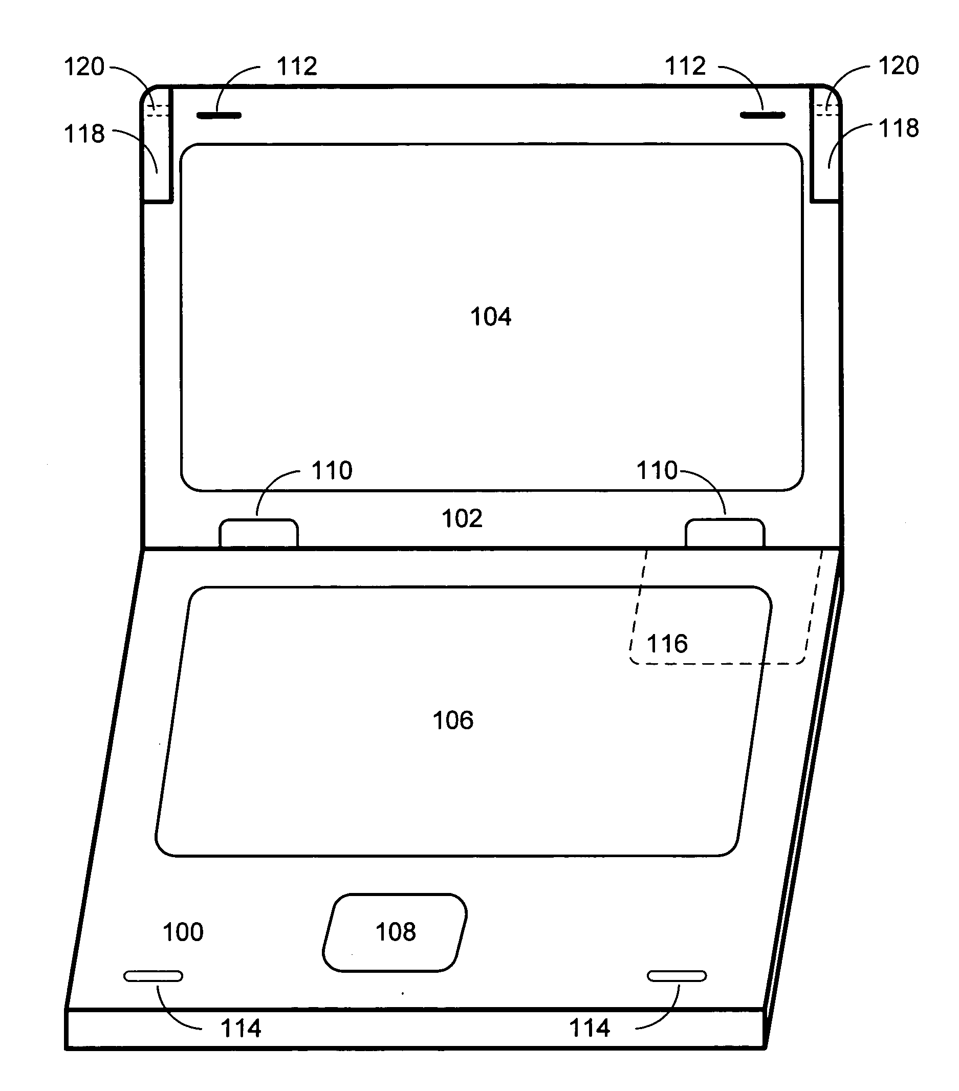
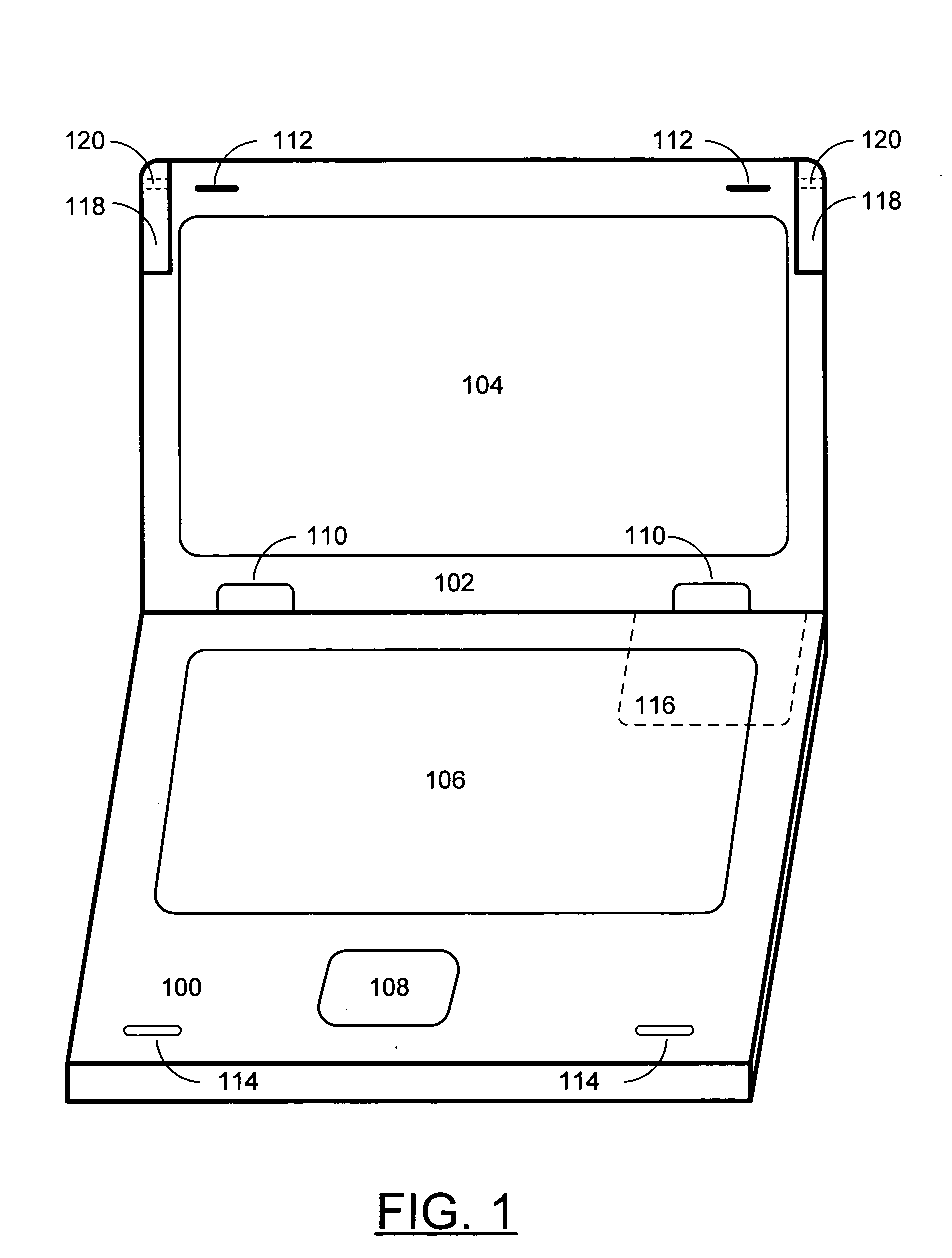
[0010]FIG. 1 is a view of a portable electronic device including a body and a display enclosure according to the present invention. In an example embodiment of the present invention, a portable electronic device including a body 100, and a display enclosure 102 is provided. Within the display enclosure 102 is a display 104. The body 100 includes a keyboard 106 and a touch pad 108. The display enclosure 102 is mechanically coupled to the body 100 by two hinges 110. When closed, the display enclosure 102 is locked to the body 100 by two latches 112 which lock into latch receptacles 114 within the body 100. Within the body 100 is a wireless network device 116 used to communicate with any available wireless network. The display enclosure 102 also includes two WAN antennas 118 mechanically coupled to the display enclosure 102 by two pins 120 in such a manner that the WAN antennas 118 may rotate about the pins 120 such that when rotated they extend above the top of the display enclosure 1...


PUM


Abstract

A portable electronic device, including a base mechanically coupled to a display enclosure with a hinge, is built. The display enclosure includes at least one WAN antenna configured to rotate about an axis such that when closed the antenna forms part of the display enclosure, and when rotated to an open position the antenna extends above the display enclosure.

Description

FIELD OF THE INVENTION [0001] The present invention relates generally to the field of wireless networks and more specifically to RF antennas for use in wireless networks. BACKGROUND OF THE INVENTION [0002] As wireless networks become more and more common, many mobile computing devices are incorporating network hardware within the portable computer. Signal integrity correlates to network speed so designers work to provide effective RF antennas within portable electronic devices in such ways that signal integrity is maximized. Prior solutions include the use of external RF antennas that electrically couple to the portable device, or the placement of RF antennas within a display enclosure. External RF antennas require the portable device to provide an external RF antenna connector, taking up valuable space on the exterior of the enclosure. Also, external RF antennas are vulnerable to damage since they are typically attached along one of the sides of the enclosure where they may inadver...

Claims


Application Information

Patent Timeline
Patent Type & Authority Applications(United States)
IPC IPC(8): H01Q1/24
CPCH01Q1/084H01Q1/241
Inventor DOCZY, PAUL J.MOORE, EARL W.WOLFF, STACY L.
Owner HEWLETT PACKARD DEV CO LP
Why Eureka
Try Eureka