Constant-temperature fluid supply system

a fluid supply system and constant temperature technology, applied in the direction of refrigeration machines, machines using electric/magnetic effects, domestic cooling apparatus, etc., can solve the problems of inability to control the temperature of water, the inability to control the accuracy of target devices, and the inability to achieve high degree of accuracy

Inactive Publication Date: 2006-04-27
NUFLARE TECH INC
View PDF8 Cites 11 Cited by
  • Summary
  • Abstract
  • Description
  • Claims
  • Application Information

AI Technical Summary

Problems solved by technology

Those kinds of water are not controlled in temperature, and their temperatures inevitably vary.
This problem is marked in the case of the cooling water for use in a chiller unit.
Since this results in a change in the temperature of the constant-temperature water, the target devices cannot be controlled with a high degree of accuracy.
As discussed above, the conventional constant-temperature fluid supply apparatus has problems in that the temperature of the constant-temperature fluid varies due to temperature variations of the externally-provided cooling water.

Method used


Image

  • Constant-temperature fluid supply system
  • Constant-temperature fluid supply system
  • Constant-temperature fluid supply system

Examples


first embodiment

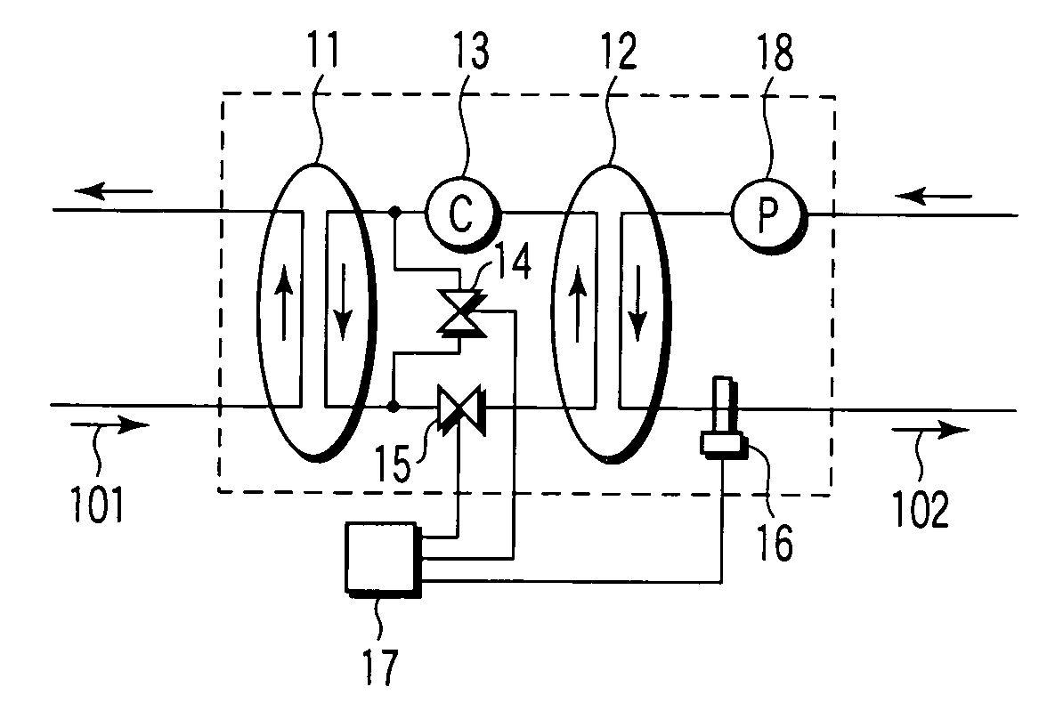
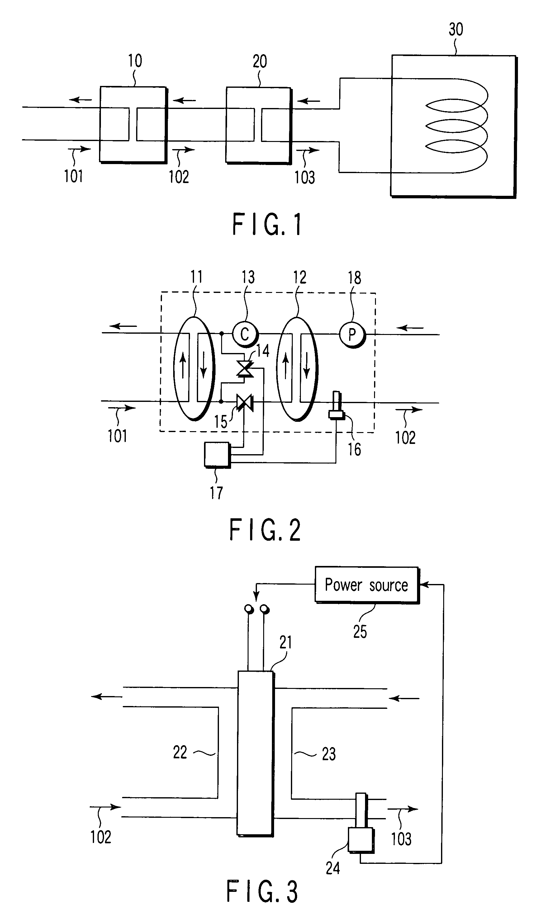
[0030] In FIG. 1, reference numeral 10 denotes a first constant-temperature fluid supply apparatus. Cooling water 101 (i.e., cooling fluid), which is tap water or circulation water in plants, is supplied to the input side of the apparatus 10. First constant-temperature water 102 (i.e., a first constant-temperature fluid) is output from the output side of the apparatus 10. Reference numeral 20 denotes a second constant-temperature fluid supply apparatus. First constant-temperature water 102 is supplied to the input side of the apparatus 20 as cooling water. Second constant-temperature water 103 (i.e., a second constant-temperature fluid) is output from the output side of the apparatus 20. The second constant-temperature water 103 is supplied to an external apparatus 30 (i.e., an apparatus whose temperature is to be kept constant), for maintaining its constant temperature.

[0031] The first and second constant-temperature fluid supply apparatuses 10 and 20 are connected together by mea...

second embodiment

[0043]FIG. 5 is a schematic diagram showing a constant-temperature fluid supply system according to the second embodiment. In FIG. 5, similar or corresponding structural elements are denoted by the same reference numerals as used in FIG. 1, and a detailed description of such structural elements will be omitted herein.

[0044] The second embodiment differs from the first embodiment in that the first constant-temperature water 102 from the first constant-temperature fluid supply apparatus 10 is supplied to not only to the second constant-temperature fluid supply apparatus 20 but also to an external apparatus 301. In other words, part of the first constant-temperature water 102 is circulated between the first fluid supply apparatus 10 and the external apparatus 301. With this structure, the temperature of external apparatus 301 can be kept at a constant value to a certain extent (the temperature of external apparatus 301 cannot be so accurately controlled as the temperature of external ...

third embodiment

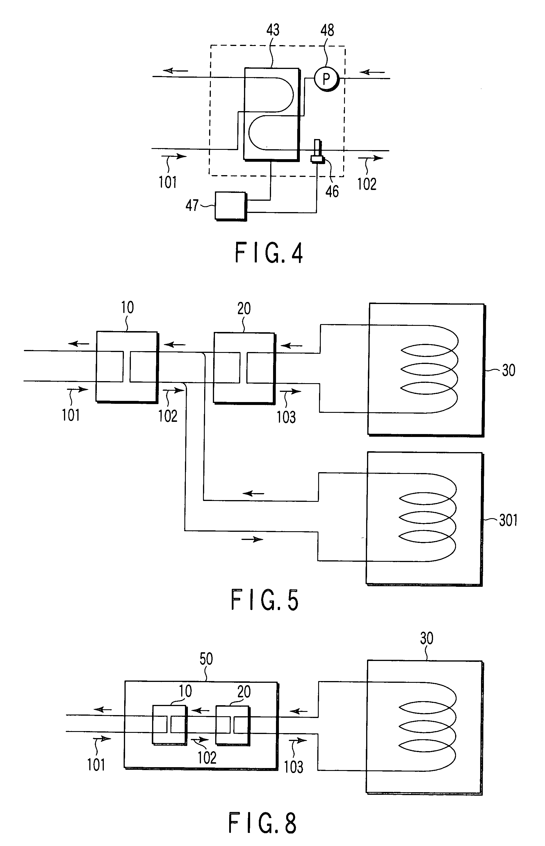
[0046]FIG. 6 is a schematic diagram showing a constant-temperature fluid supply system according to the third embodiment. In FIG. 6, similar or corresponding structural elements are denoted by the same reference numerals as used in FIG. 1, and a detailed description of such structural elements will be omitted herein.

[0047] The third embodiment differs from the first embodiment in that second constant-temperature fluid supply apparatuses 201 and 202 are provided in addition to the second constant-temperature fluid supply apparatus 20. In other words, three second constant-temperature fluid supply apparatuses 20, 201 and 202 are employed to keep the temperatures of external apparatuses 30, 301 and 302 at constant values.

[0048] In the third embodiment, the first constant-temperature water 102 is supplied to three apparatuses, namely constant-temperature fluid supply apparatus 20, constant-temperature fluid supply apparatus 201 and constant-temperature fluid supply apparatus 202. As i...


PUM


Abstract

A constant-temperature fluid supply system is provided with a first constant-temperature fluid supply apparatus and a second constant-temperature fluid supply apparatus. The first constant-temperature fluid supply apparatus has an input side to which a cooling fluid not controlled in temperature is supplied, and an output side from which a first constant-temperature fluid having a stable temperature is supplied. The second constant-temperature fluid supply apparatus has an input side to which the first constant-temperature fluid is supplied, and an output side from which a second constant-temperature fluid having a more stable temperature than that of the first constant-temperature fluid is supplied.

Description

CROSS-REFERENCE TO RELATED APPLICATIONS [0001] This application is based upon and claims the benefit of priority from prior Japanese Patent Applications No. 2004-309705, filed Oct. 25, 2004; and No. 2005-299606, filed Oct. 14, 2005 the entire contents of both of which are incorporated herein by reference. BACKGROUND OF THE INVENTION [0002] 1. Field of the Invention [0003] The present invention relates to a constant-temperature fluid supply system adapted for use in a semiconductor manufacturing apparatus and configured to control the temperature of a target device with a high degree of accuracy. [0004] 2. Description of the Related Art [0005] Devices that have to be kept at constant temperatures are provided with an internal fluid passage for constant-temperature water. By circulation of the constant-temperature water supplied from constant-temperature fluid supply sources, the devices can be kept in the constant-temperature state. In other words, the temperatures of the devices can...

Claims


Application Information

Patent Timeline
Patent Type & Authority Applications(United States)
IPC IPC(8): F25D17/02
CPCF25B21/02F25B2321/0212F25B2321/0252F25D17/02
Inventor NISHIYAMA, TETSUROHONDA, TAKKAKISAITO, HIDEOYASUDA, SATOSHITAKEKUMA, HIDEKI
Owner NUFLARE TECH INC
Why Eureka
Try Eureka