Fluid flow regulation of a vehicle shock absorber/damper

a technology of vehicle shock absorber and fluid flow, which is applied in the direction of shock absorber, liquid based damper, vibration damper, etc., can solve the problems of insufficient use of air flow past the damper, and the cavitation of the oil within the damper itsel

a technology of vehicle shock absorber and fluid flow, which is applied in the direction of shock absorber, liquid based damper, vibration damper, etc., can solve the problems of insufficient use of air flow past the damper, and the cavitation of the oil within the damper itsel

US20060096817A1Active Publication Date: 2006-05-11THYSSENKRUPP BILSTEIN OF AMERICA

Image

  • Fluid flow regulation of a vehicle shock absorber/damper
  • Fluid flow regulation of a vehicle shock absorber/damper
  • Fluid flow regulation of a vehicle shock absorber/damper

Examples


Embodiment Construction

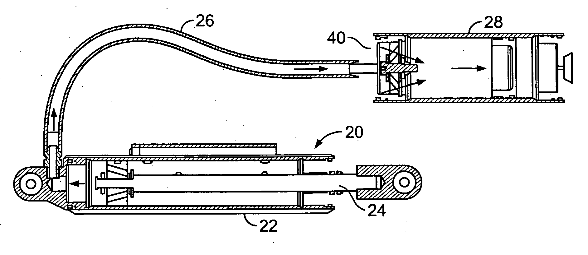
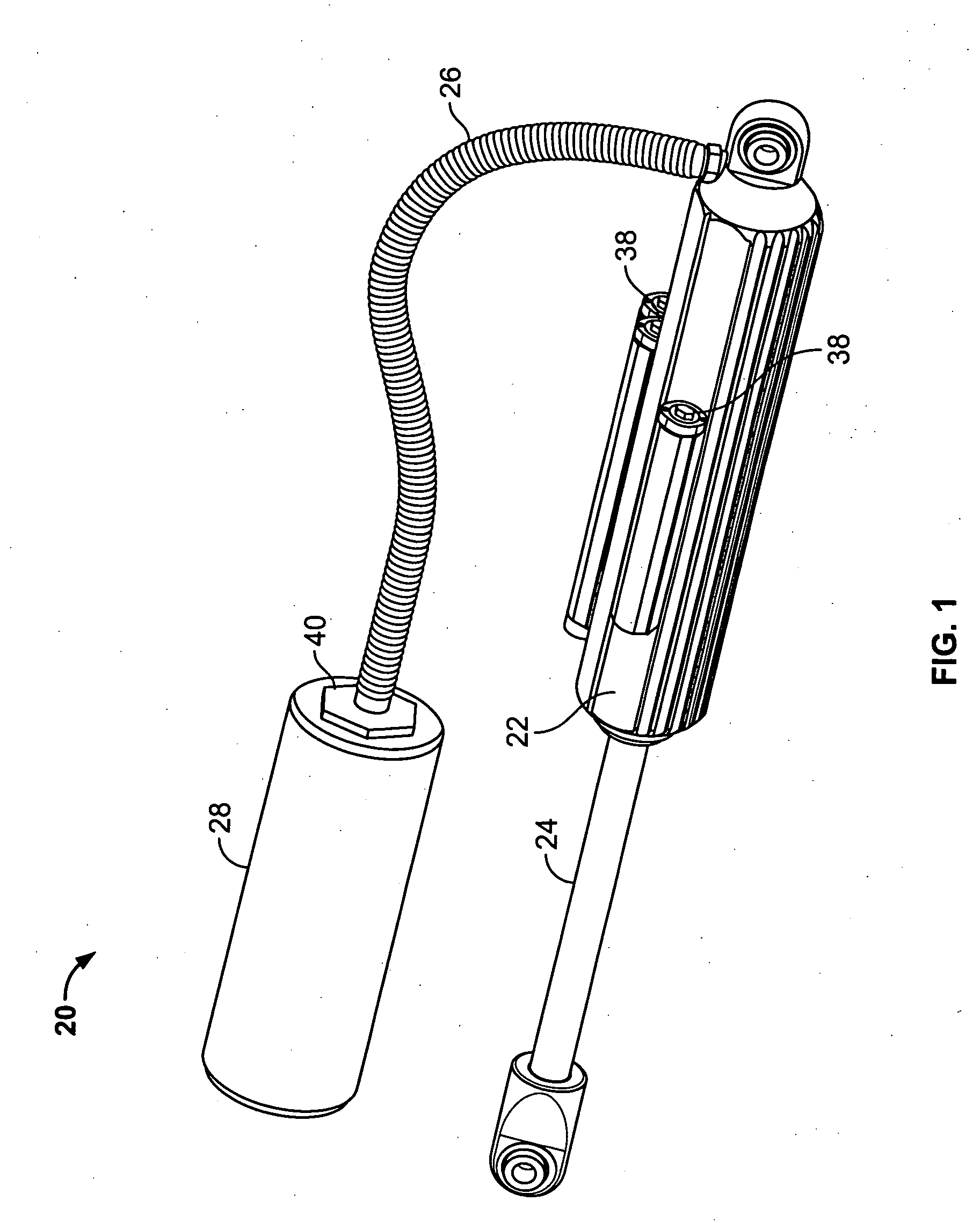
[0035] Off-road racing vehicles include those in a truck-race, buggy-race, lifted truck recreational, sand car-recreational, monster truck and military specialty vehicles. The function of the shock absorber 20 (FIG. 1) of the invention is to permit such off road racing vehicles to pass over extremely rough terrain at high speeds with improved control and stability.

[0036] The shock absorber 20 includes a radial bypass damper housing 22 having a chamber in which moves a working piston and shaft 24 to effect compression and rebound strokes. A hose 26 connects the opposite end of the chamber with an oil gas reservoir 28.

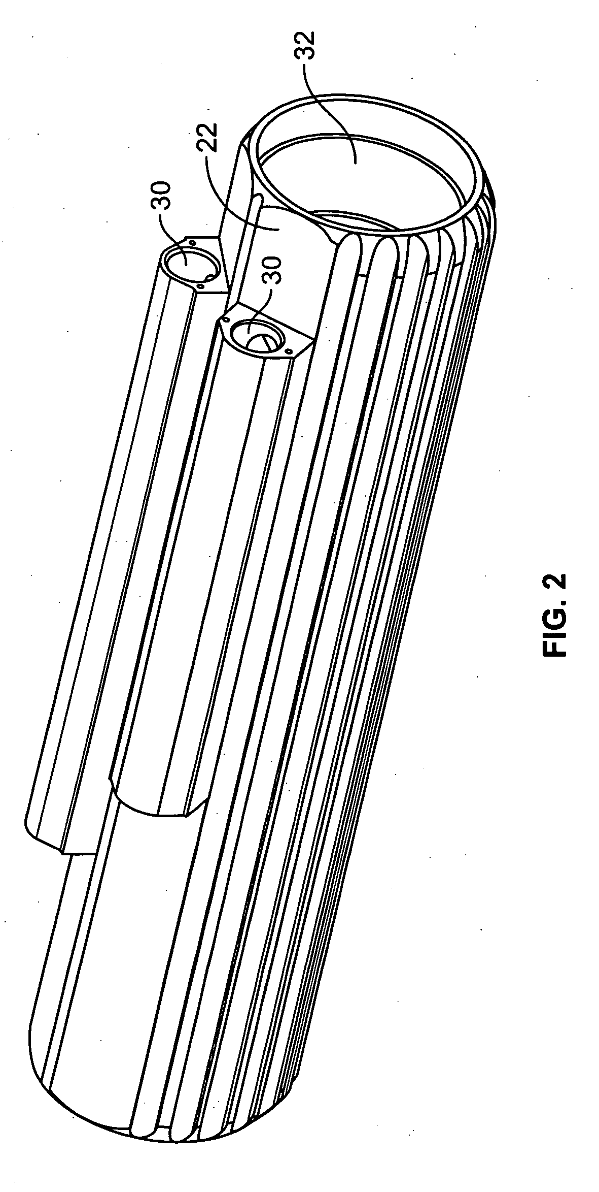
[0037] Turning to FIG. 2, the radial bypass damper housing 22 is made of aluminum alloy and formed without welds. The housing of the radial bypass damper housing 22 may be formed from extruded 6061-T6 aluminum alloy that is manufactured in solid profile in fixed lengths. The profile of the radial bypass damper housing 22 incorporates cooling fins, which in turn offer s...


PUM


Abstract

Shock absorber components, such as a radial bypass damper, an anti-cavitation valve (ACV) and an incremental flow metering valve IFMV. The damper is of a continuous, unitary construction with a main hole and auxiliary holes interconnected by passageways. The ACV has openings that angle obliquely relative to entry surfaces of valving shims and extend at an incline continuously through the valving shims. The metering valve linearly regulates flow, substantially independent of piston displacement.

Description

BACKGROUND OF THE INVENTION [0001] The present invention relates to position sensitive radial bypass damper (RBD) components that regulate gas / oil flow of an off road vehicle shock absorber. Such components may include a radial bypass damper housing, an anti-cavitation valve (ACV), and an incremental flow metering valve (IFMV). [0002] Vehicle suspension undergoes dynamic movements as it negotiates obstacles generally found in off-road racing venues. Shocks are provided to control wheel movement by resistance in off-road vehicles with such suspension. Such resistance arises from pressure forming on the compression side of the working piston during the compression stroke and on the rebound side of the piston during the rebound stroke. The nitrogen chamber, separated from the hydraulic oil by a floating dividing piston, provides an opposing force on the said oil during the dynamic functions of the damper. Oil displacement and directional forces compress and expand the nitrogen chamber ...

Claims


Application Information

Patent Timeline
11 May 2006
Publication
US20060096817A1
IPC
F16F9/34
CPC
F16F9/3235; F16F9/44
Inventors
NORGAARD, BRET M.; CIMINS, DOUGLAS J.