Contact cooling device

a cooling device and contact technology, applied in the direction of cooling/ventilation/heating modifications, lighting and heating apparatus, electrical apparatus, etc., can solve the problems of failure or destruction of these devices, and the need for effective heat removal techniques in this area, so as to eliminate an expensive machining operation

Inactive Publication Date: 2006-05-25
LYTRON
View PDF23 Cites 28 Cited by
  • Summary
  • Abstract
  • Description
  • Claims
  • Application Information

AI Technical Summary

Benefits of technology

[0011] During the disclosed process for making the disclosed device, the stacked plates are placed in a fixture and diffusion bonded in a vacuum or inert atmosphere. A mechanical load is applied to maintain contact pressure between the plates during this process. The fixture used for diffusion bonding the plates together can al

Problems solved by technology

As it is generally known, overheating of various types of electronic components may result in their failure

Method used


Image

  • Contact cooling device
  • Contact cooling device
  • Contact cooling device

Examples


Embodiment Construction

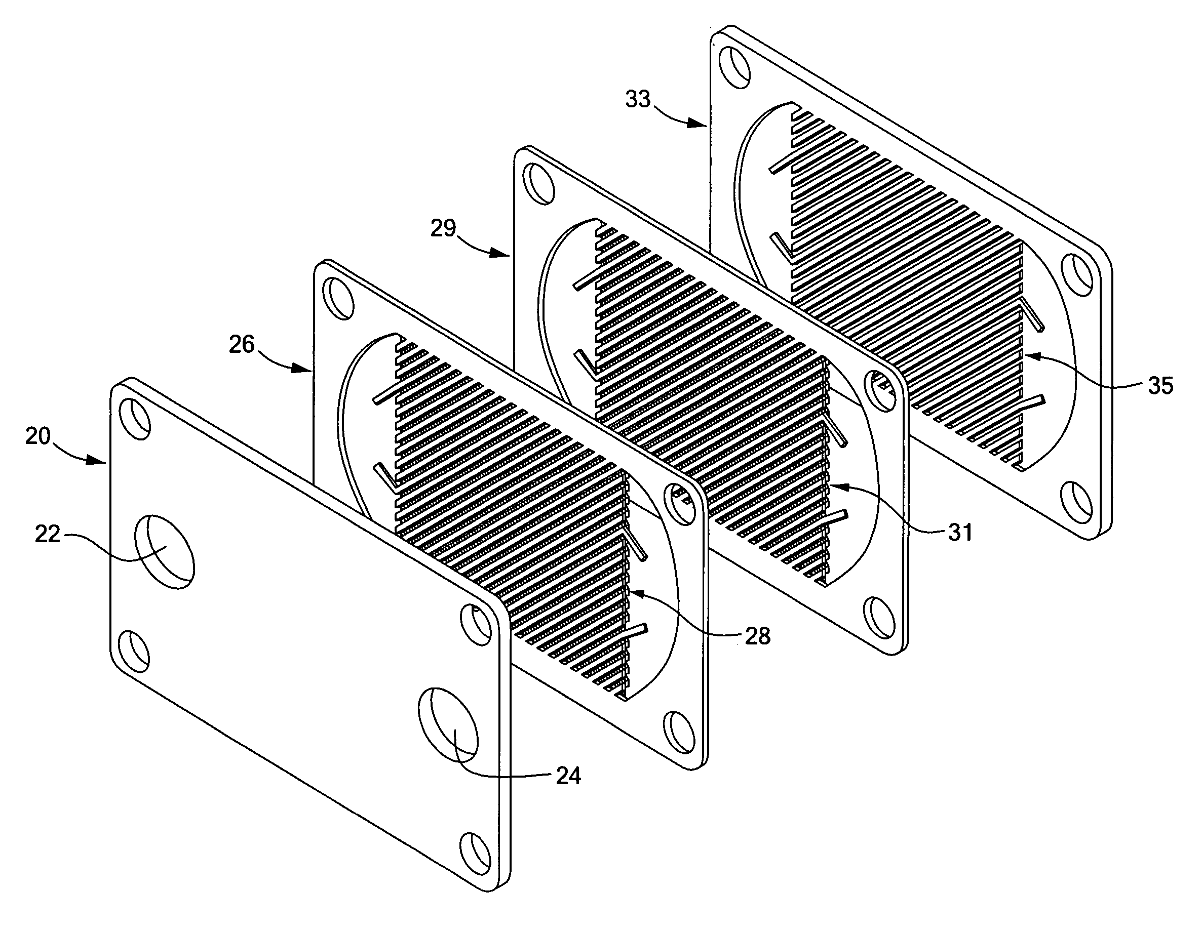
[0023] A high performance cooling device is disclosed, which may, for example, be fabricated using an assembly of relatively thin (0.040″-0.100″) copper plates that each include a pattern having a number of fluid flow channels. The pattern may be formed on the patterned plates using any appropriate technique, for example by photo-etching, stamping, forging, casting or other processes.

[0024]FIG. 1 shows an example embodiment 10 of the disclosed cooling device. As shown in FIG. 1, a first set of channels 12 are defined by a first plate within the device 10, while a second set of channels 14 are defined by a second plate within the device 10. In the illustrative embodiment of FIG. 1, the flow channels 12 and 14 have been formed in corresponding copper plates to form the patterned plates stacked within the resulting device 10.

[0025]FIG. 1 further shows a fluid inlet port 18 allowing fluid to pass into the device, an input coolant distribution plenum 16 for passing fluid to the channel...


PUM

PropertyMeasurementUnit
Angleaaaaaaaaaa
Angleaaaaaaaaaa
Angleaaaaaaaaaa

Abstract

A high performance cold plate cooling device including multiple, relatively thin plates, each having patterns formed thereon that, as arranged within the device, cause turbulence in a fluid passing within the cooling device. Adjacent plates within the cooling device are arranged such that fluid channels within their patterns are arranged crosswise. One or more barriers extending at least a portion of the length of the device separate the crosswise channels into two or more flow sections and increase uniformity of thermal performance over the active plate area. Manufacturing of the device includes stacking the plates in an alternating fashion such that the channels within the pattern of each plate are crosswise with respect to the channels in the pattern of an adjacent plate and adjacent barrier walls abut.

Description

CROSS REFERENCE TO RELATED APPLICATIONS [0001] This application claims priority under 35 U.S.C. §119(e) to U.S. Provisional Patent Application No. 60 / 371,883, entitled “Contact Cooling Device,” filed Apr. 11, 2002, the disclosure of which is incorporated by reference herein. [0002] This application is a continuation-in-part of U.S. patent Ser. No. 10 / 412,753, entitled “Contact Cooling Device,” filed Apr. 11, 2003, the disclosure of which is incorporated by reference herein.STATEMENT REGARDING FEDERALLY SPONSORED RESEARCH OR DEVELOPMENT [0003] N / A BACKGROUND OF THE INVENTION [0004] The present invention relates generally to a cooling apparatus and more specifically to a design for a contact cooling device operable to introduce turbulence into a cooling fluid for improved cooling characteristics. [0005] As it is generally known, overheating of various types of electronic components may result in their failure or destruction. The need for effective heat removal techniques in this area ...

Claims


Application Information

Patent Timeline
IPC IPC(8): H05K7/20F28F13/12
CPCF28F13/12Y10T29/49366Y10T29/49378F28F3/12F28F3/048
Inventor GOLDMAN, RICHARDAKSELBAND, BORISGERBUTAVICH, CHARLESCARSWELL, CHARLES
Owner LYTRON
Why Eureka
Try Eureka