Air dryer system and method employing a jet engine

a technology of air dryer and jet engine, which is applied in the direction of furnaces, lighting and heating apparatus, separation processes, etc., can solve the problems of high cost of thermal drying systems and large air and heat production, and achieve the effect of high quality, efficiency and operating cos

Inactive Publication Date: 2006-03-16
STAPLES WESLEY A
View PDF12 Cites 5 Cited by
  • Summary
  • Abstract
  • Description
  • Claims
  • Application Information

AI Technical Summary

Benefits of technology

[0008] In view of the foregoing background, the present invention provides a process for producing a high quality dried product. Objects of the present invention may be achieved by employing a power plant, in the form of a turbofan jet engine, in an air-drying system that may use both thermal and non-thermal air-drying. The power plant may produce large quantities of air and heat, and operate with efficiency and an operating cost that provides a system suitable for use in situations for which existing thermal drying systems are too costly to operate.

Problems solved by technology

The power plant may produce large quantities of air and heat, and operate with efficiency and an operating cost that provides a system suitable for use in situations for which existing thermal drying systems are too costly to operate.

Method used


Image

  • Air dryer system and method employing a jet engine
  • Air dryer system and method employing a jet engine
  • Air dryer system and method employing a jet engine

Examples


Embodiment Construction

[0039] The present invention will now be described more fully hereinafter with reference to the accompanying drawings, in which preferred embodiments of the invention are shown. This invention may, however, be embodied in many different forms and should not be construed as limited to the embodiments set forth herein. Rather, these embodiments are provided so that this disclosure will be thorough and complete, and will fully convey the scope of the invention to those skilled in the art. Like numbers refer to like elements throughout, and prime notation is used to indicate similar elements in alternate embodiments.

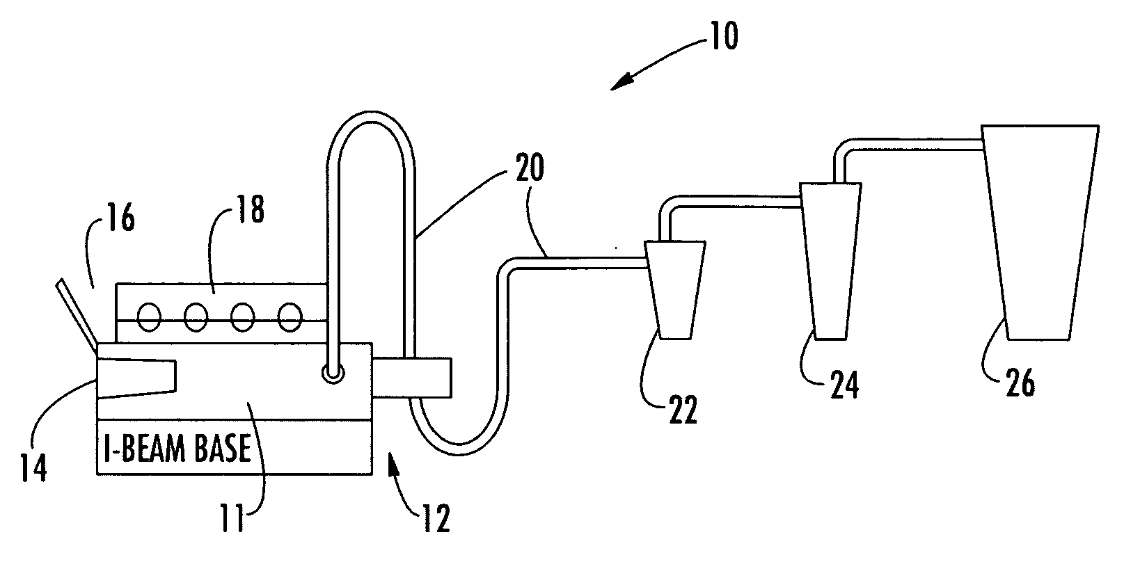
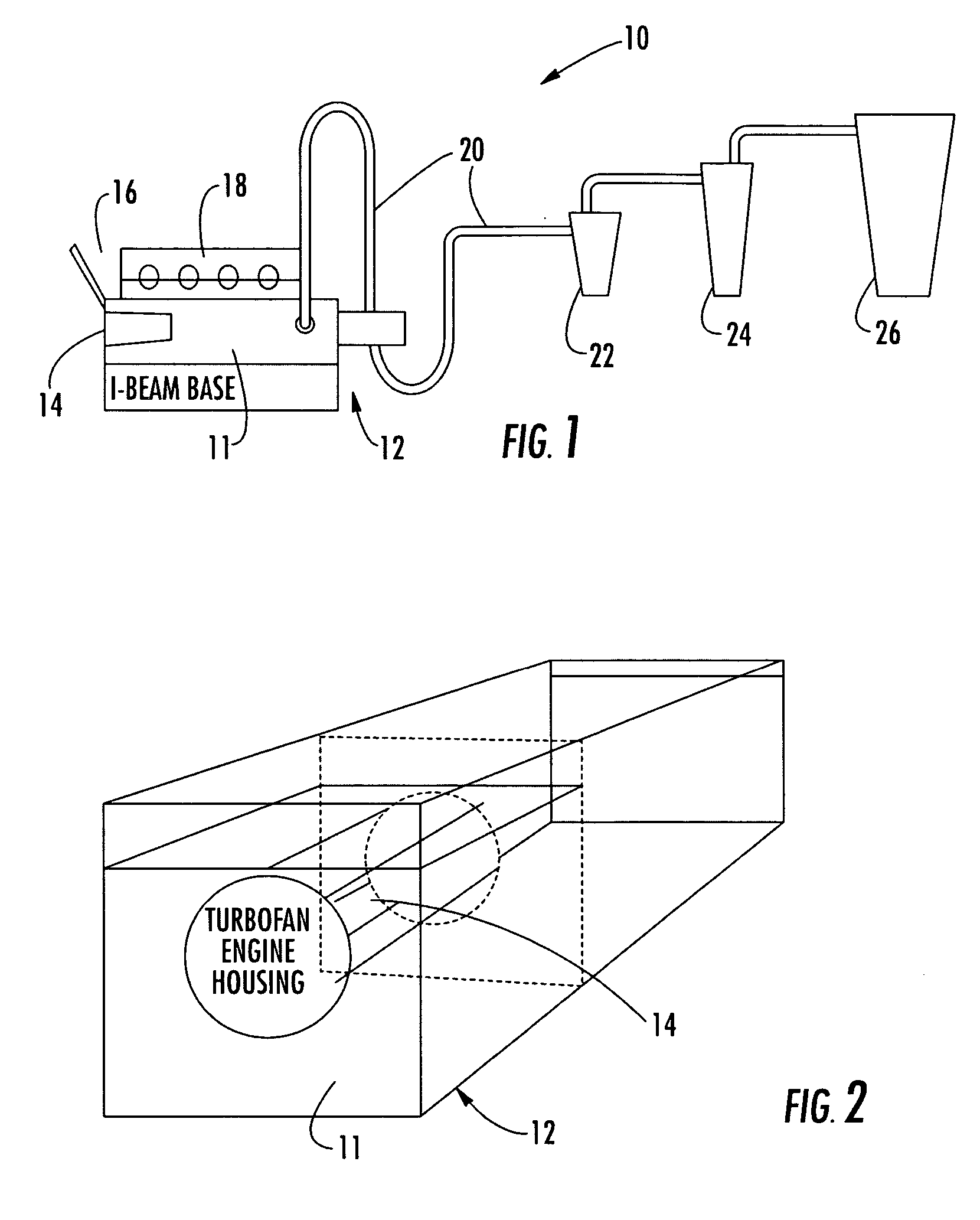
[0040] Referring initially to FIG. 1, components an air-dryer apparatus 10 according to the present invention are shown. A housing 12 includes an air distribution chamber 11 is provided at the front end of the apparatus 10. The chamber 11 has mounted therein a jet engine 14, such as a turbofan jet engine, by way of example.

[0041] The structure and operating characteristics...


PUM


Abstract

An air dryer and process employs a jet engine for producing high quality dried products. A turbofan jet engine in an air-drying system uses both thermal and non-thermal air-drying. The turbofan jet engine is housed within an air distribution chamber for directing exhaust air and bypass air from the jet engine into a product drying tube, where it is dried through a combination of thermal drying from heat content in an engine exhaust, and by the kinetic energy of air flowing past the product traveling through the drying tube, that may include a physical impediment for retarding retard the speed of the product solids flowing in the air stream through the tube.

Description

CROSS-REFERENCE TO RELATED APPLICATIONS [0001] This application is a continuation application of U.S. Utility application Ser. No. 10 / 975,032, filed Oct. 27, 2004, which claims the benefit of U.S. Provisional Application No. 60 / 514,477, filed Oct. 27, 2003, the disclosures of which are hereby incorporated by reference herein in their entireties, all commonly owned.FIELD OF THE INVENTION [0002] The present invention generally relates to industrial dryers and in particular to a dryer employing a jet engine as a source of heat and air. BACKGROUND OF THE INVENTION [0003] Many different types of commercial and production endeavors require that a primary product produced and / or by-products thereof are to be dried at a stage after production process. Drying is generally needed in, for example, food processing, fertilizer production, sludge removal and processing, chip and bark processing, agriculture manure processing, and in the processing of distiller's grain, cotton, soybean hulls, mine...

Claims


Application Information

Patent Timeline
Patent Type & Authority Applications(United States)
IPC IPC(8): F26B3/00F26B19/00F26B17/00F26B11/00F26B17/10
CPCF26B17/103
Inventor STAPLES, WESLEY A.
Owner STAPLES WESLEY A
Why Eureka
Try Eureka