Method and apparatus for washing pulp by means of intensified suction

a technology of intensified suction and pulp, which is applied in the direction of moving filter element filters, filtration separation, separation processes, etc., can solve the problems of releasing or otherwise damaging the pulp layer, limiting the vacuum intensity, and reducing so as to reduce the amount of liquid and impurities contained in the pulp layer, the effect of increasing the discharge consistency of the filter

Active Publication Date: 2014-12-04
ANDRIZ OY
View PDF6 Cites 6 Cited by
  • Summary
  • Abstract
  • Description
  • Claims
  • Application Information

AI Technical Summary

Benefits of technology

[0028]If the intensified suction is directed to sectors located on both sides of the suspension surface level, this is most advantageously accomplished by means of a common channel in the suction side. Filtrates coming from these sectors are highly similar in quality and can thus be led into a same process or container. Preferably this zone of intensified suction is focused so that the midpoint of the valve opening is located at a spot corresponding to the surface level in the basin, whereby both of these sectors providing special advantage are of approximately equal size. This size difference between the sectors may be 10 degrees for optimizing the process.
[0029]In the drying stage, after the last washing pipe, where the pulp web is dried to the final consistency, the intensified suction provides clear advantages. A boosted suction increases the discharge consistency of the filter and thus decreases the amount of liquid and impurities contained in the pulp. In the drying stage, compaction of the pulp layer subjected to intensified suction and absorption of air do not hamper the functioning of the stage. The intensity of the vacuum can be limited, especially with fiber materials, by too compact and dry pulp which can be so strong and rigid that it may be peeled off the drum prior to the discharge stage, pushed by the scraper. On the other hand, intensified suction keeps the pulp layer better on the surface of the drum, so that the pulp can be dried to a higher dryness than usual.
[0030]A high discharge consistency is especially advantageous when washing brown stock, which after that is led to bleaching or in a situation where process conditions of different treatment stages change considerably as to pH or another variable. Due to intensified suction, the sector needed for the drying stage can be narrowed, i.e. a wider sector can be arranged for the washing stage, correspondingly, e.g. by adding an extra washing pipe or making changes in the flow or orientation or the washing liquid spray.
[0031]By means of the widened washing stage due to intensified suction, the washing stage is substantially prolonged. This is advantageous also in view of increasing the rotational speed, because the duration of the washing stage is essential in view of the washing result. If intensified suction is directed also to a stage where the surface of the drum is still in the basin, the thickness of the filtered pulp layer and its consistency can be increased prior to washing. These improvements allow increasing the capacity by increasing the rotational speed of the drum and thus by increasing the amount of washed pulp, while the layer thickness remains at least unchanged, and simultaneously maintaining an earlier or a desired washing efficiency. A sector of intensified suction also allows forming a thicker pulp layer and efficient washing thereof.
[0032]From separate zones of intensified suction, the withdrawn filtrates can be distributed under control to be used most preferably as such or slightly treated in various processes, most advantageously in the same washer or as process or washing liquid of upstream treatment stages. The filtrate of the drying stage is most suitable with intensified washing, to be used in the same washer in the initial stage of washing, e.g. in the first two washing pipes. Various embodiments of the invention allow intensifying the washing, so that in the initial stage thereof liquids of poorer quality can be used, if the quality requirements allow that.
[0033]If an adjustable positioning of the valve is used in the suction head of the drum for controlling the suctions and filtrates, the directing of the intensified suction can be optimized in various situations, in addition to the control of the vacuum level. Directing intensified suction earlier to the zone within the basin increases the layer thickness and thus the capacity. Changes in the suspension surface level can be compensated. After rising from the suspension surface, terminating the intensified suction later can intensify the washing. The quality of the pulp in the basin, the fiber length and fiber content as well as variations in the quality requirements set for washed pulp, and other changes in the conditions can be controlled even when the apparatus in is operation by means of adjusted timing. If a valve is used, in which the surfaces limiting the zones can be separately positioned, or if replaceable valve components are used having various timings, the initial and terminal points of the intensified suction can be controlled separately. Thus the operation of the expensive washer can be remarkably intensified, controlled and optimized.

Problems solved by technology

Further, in this stage liquid in the pulp layer possibly flowing in the direction of the layer or out of there and suspension flows in the basin can cause releasing of the layer from the drum.
Directing a strong flow of washing liquid onto the surface of the pulp layer too early, before the pulp layer has settled firmly enough onto the surface of the drum can release or otherwise damage the pulp layer.
However, it has its limitations.
A major pressure difference may excessively tighten an especially fiber-containing pulp layer, whereby its capability of penetrating the pulp suspension or washing liquid is decreased.
At the beginning, a minor pressure difference through the pulp layer and the filtering surface is adequate for filtrate flow and even hydrostatic pressure alone, and too efficient a suction withdraws solid material through the filtering surface excessively.
Generating a stronger suction consumes excessively energy if accomplished with pumps.
Suitable pumps with a large volume flow are significantly expensive.
Operational advantage obtained by more efficient suction would lead to higher investment and operational expenses.
Strong suction obtained by lengthening the suction leg could lead to excess alteration of the suction due to increased vaporization of water and absorption of gases.
The washing tube spraying washing liquid onto the pulp layer and the point of spraying cannot be located down to the vicinity of the suspension surface, since that would lead to release or damage of the filtered layer.
Thus, in this sector the current situation is harmful for the operation of the apparatus.
This limits the duration of the washing stage.
Sectors of intensified suction that are wider than these sectors do not necessarily bring any benefit, since as the volume flows grow, fixed costs and operational costs can rise sharply.
Since expense reasons and liquid treatment capacity often limit the use of clean liquid, the use of the cleanest filtrate as washing liquid as such increases the amount of available washing water.
The intensity of the vacuum can be limited, especially with fiber materials, by too compact and dry pulp which can be so strong and rigid that it may be peeled off the drum prior to the discharge stage, pushed by the scraper.

Method used


Image

  • Method and apparatus for washing pulp by means of intensified suction
  • Method and apparatus for washing pulp by means of intensified suction
  • Method and apparatus for washing pulp by means of intensified suction

Examples


Embodiment Construction

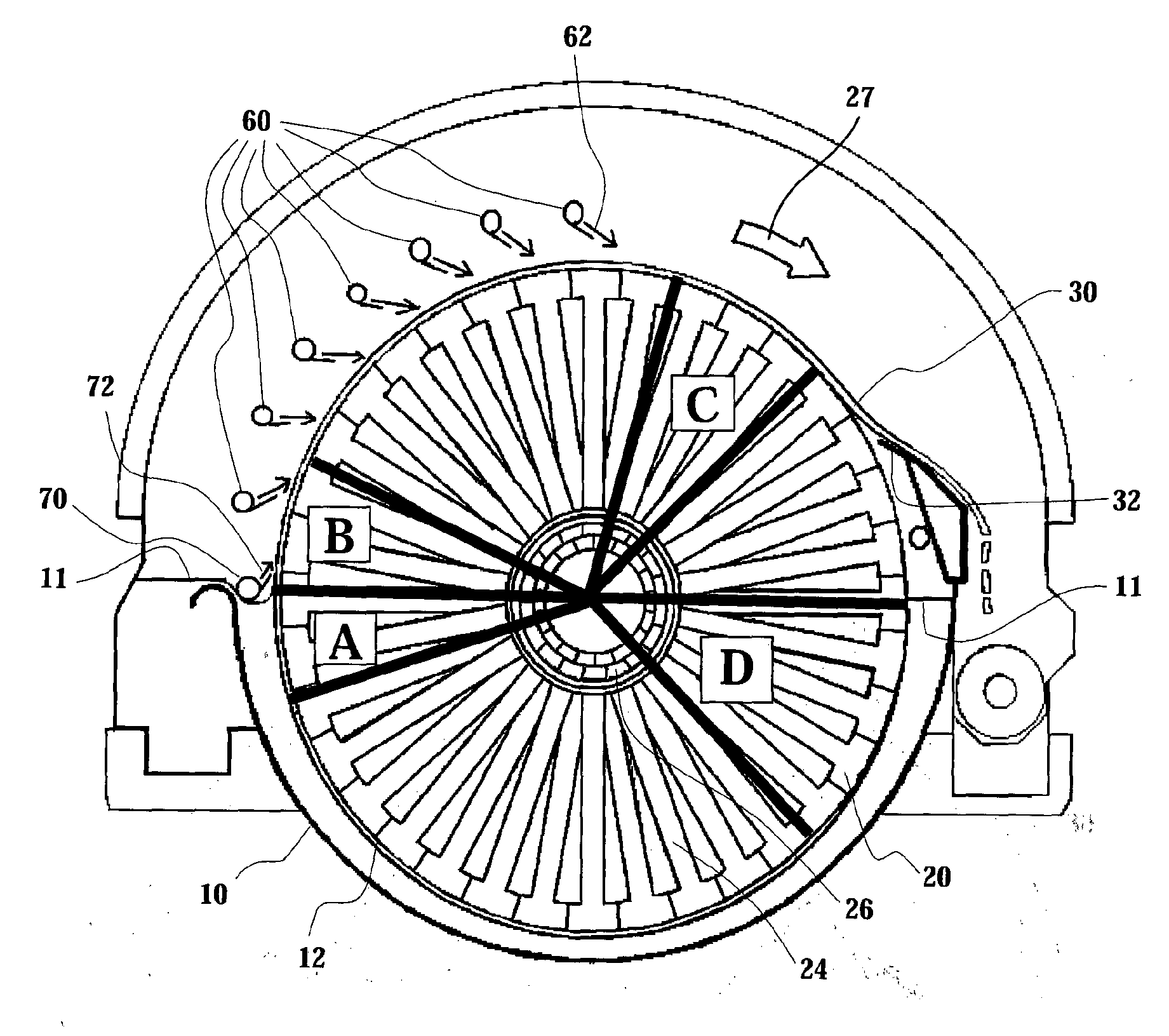
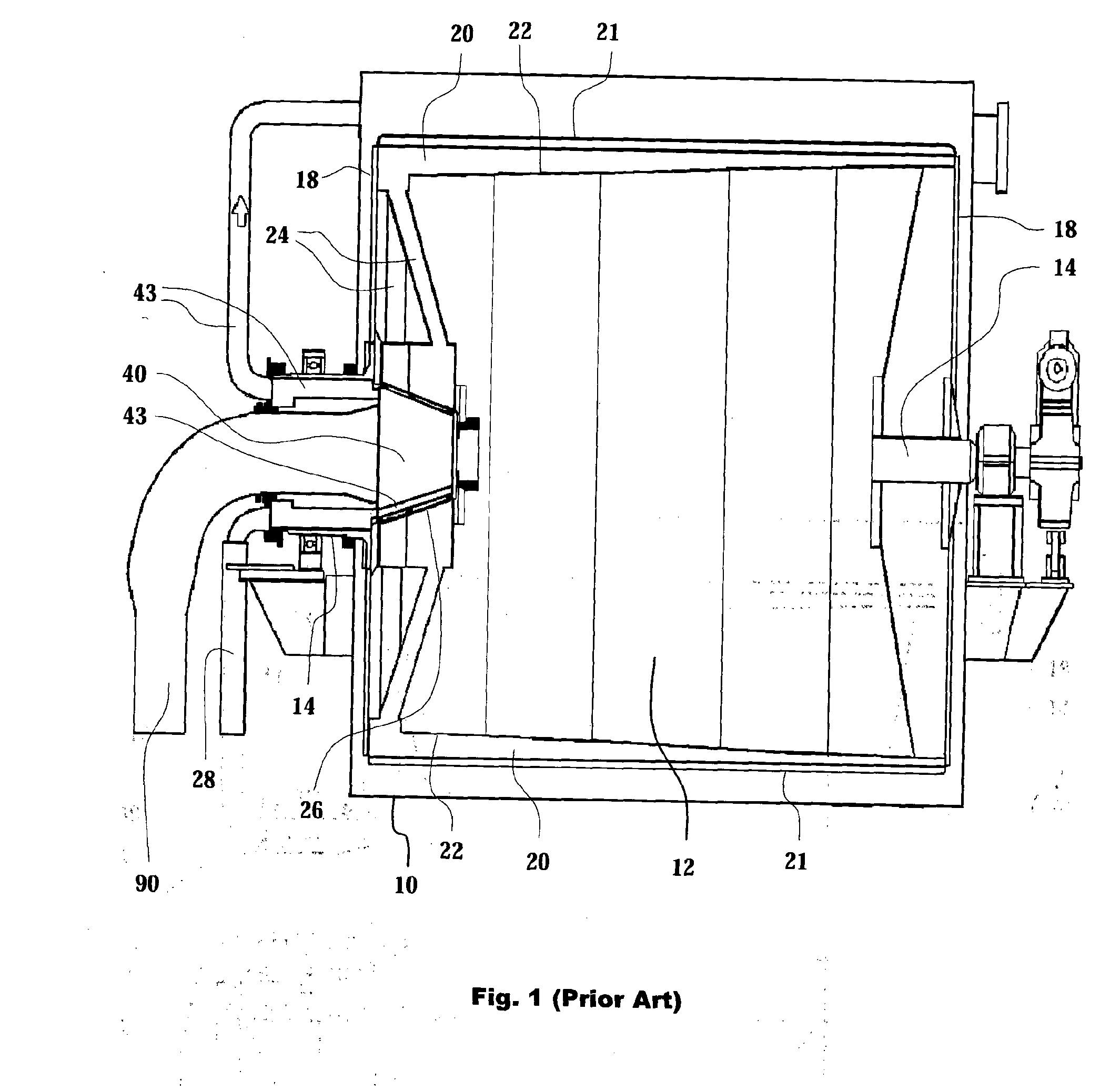
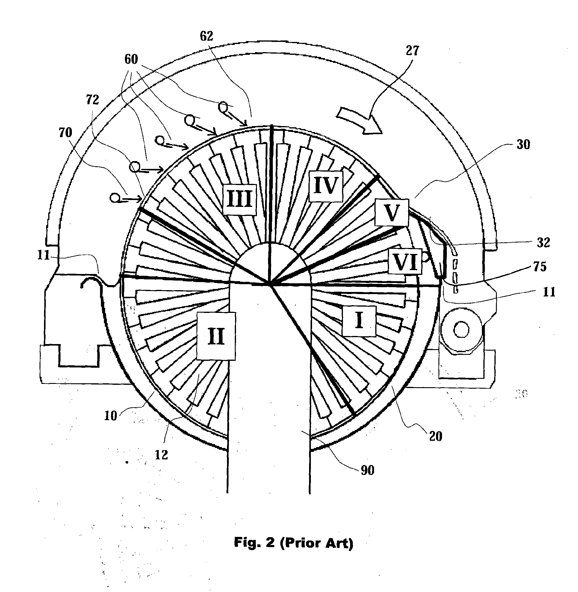
[0053]FIG. 1 illustrates a suction drum washer of prior art in a longitudinal cross section view. A filter solution with a corresponding structure without a washing stage is presented in patent publication FI 86963 (U.S. Pat. No. 5,264,138). The suction drum washer is comprised mainly of a basin 10, either with open or hood-covered upper part, and a cylindrical drum 12 arranged on a shaft 14, which shaft is supported on bearings at its ends and sealed with respect to the basin 10. The body of the drum 12 comprises end plates 18 connected to an extension of the shaft 14, which plates simultaneously prevent the suspension from entering into the interior of the drum, and longitudinal filtrate compartments 20, by means of which the ends of the drum are fixed to each other and which form the load-bearing structure of the drum. The cover of the filtrate compartments 20 may be either a perforated plate, upon which a wire acting as filtering surface is placed, or the wire 21 itself. The per...


PUM

PropertyMeasurementUnit
lengthaaaaaaaaaa
angleaaaaaaaaaa
suctionaaaaaaaaaa

Abstract

A method and an apparatus for washing a solids-containing suspension by means of a suction drum washer comprising a drum provided with a filtration surface, a main vacuum source such as a drop leg and washing tubes connected to the frame of the suction drum washer. A washing liquid stream is introduced by a first washing tube is directed to contact the pulp layer on the surface of the drum in a point below 10 degrees after the surface of the suspension and a vacuum of at least 0.1 bar greater than the main vacuum source, i.e. intensified suction is applied by means of a separate vacuum source to filtering surface at the contacting point of the first liquid stream and the pulp layer or maximum of 10 degrees before the contacting point. The intensified suction may be utilized also for boosting end of filtration stage (II) and drying stage (IV). Filtrate from the drying stage (IV) can be used at the same washer as a washing liquid at the first or the second washing tube.

Description

OBJECT OF THE INVENTION[0001]The present invention relates to a method and an apparatus for treating solid matter suspension with a vacuum filter. Especially the invention relates to washing a fibrous suspension such as pulp with a suction drum washer. A suction drum washer is generally used in brown stock washing, oxygen stage washing, bleaching washings and washing after screening at a chemical pulp mill.PRIOR ART[0002]Efficiency of the washing e.g. prior to oxygen delignification is important for obtaining high-quality pulp. In bleaching the washing result of an earlier stage has an influence on the chemical consumption of bleaching and the quality of the pulp. For obtaining and maintaining adequate quality on uniform level and other characteristics of the process set a number of limitations for maximizing the capacity of suction drum filters. Developing the overall capacity of the plant can also require intensification of pulp treatment and increase in the capacity without jeopa...

Claims


Application Information

Patent Timeline
Patent Type & Authority Applications(United States)
IPC IPC(8): B01D33/09B01D33/46
CPCB01D33/463B01D33/09B01D33/00B01D33/06D21C9/06D21D5/06
Inventor HARKONEN, PASIKARJALAINEN, SIMOLINTUNEN, TUOMOSAVOLAINEN, ERKKI
Owner ANDRIZ OY
Why Eureka
Try Eureka