Box-type after-treatment mixer and engine applying same

A mixer and box-type technology, which is applied to machines/engines, engine components, combustion engines, etc., can solve problems such as weakening engine output power and affecting combustion efficiency, improving emission consistency, improving mixing uniformity, and ensuring airflow. effect of speed

Pending Publication Date: 2022-04-29
WEICHAI POWER CO LTD +1
View PDF4 Cites 0 Cited by
  • Summary
  • Abstract
  • Description
  • Claims
  • Application Information

AI Technical Summary

Problems solved by technology

[0002] The main measures to reduce NOx emissions of diesel vehicles include two technical routes: 1) Exhaust gas recirculation (EGR) technology: exhaust gas recirculation can reduce the maximum combustion temperature of the engine, thereby reducing NOx emissions, but high EGR rate weakens the output power of the engine and affects combustion efficiency; 2) Selective catalytic reduction (SCR) technology

Method used


Image

  • Box-type after-treatment mixer and engine applying same
  • Box-type after-treatment mixer and engine applying same
  • Box-type after-treatment mixer and engine applying same

Examples


Embodiment 1

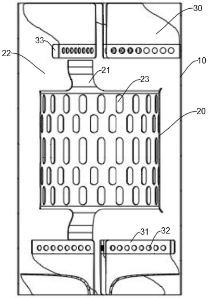
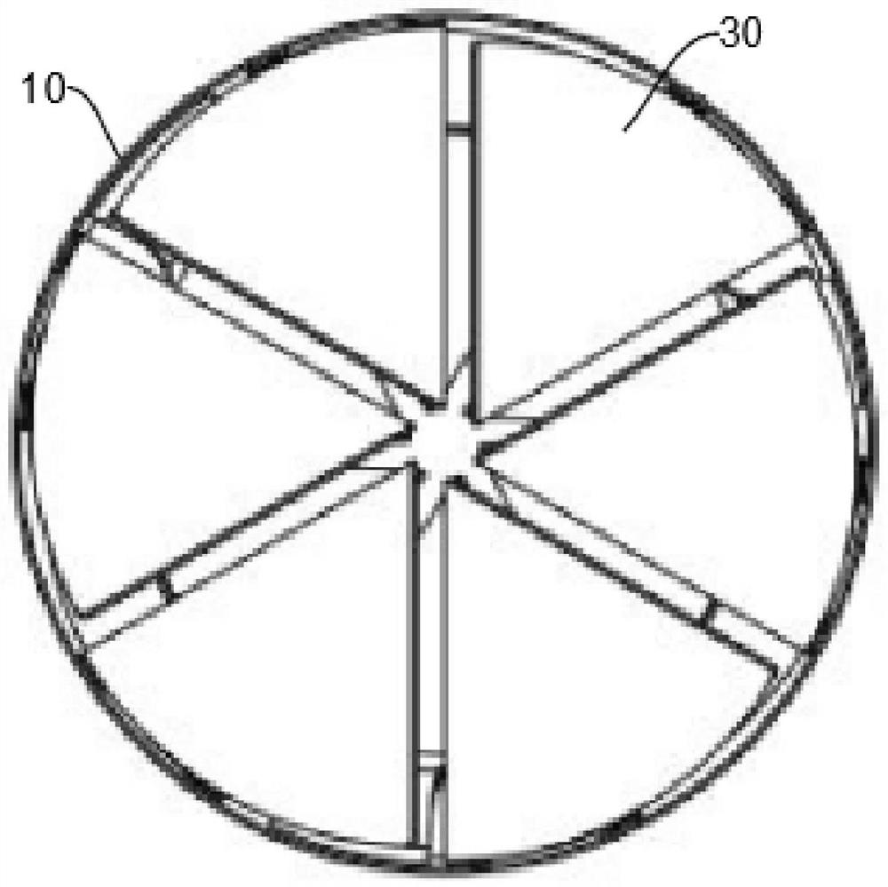
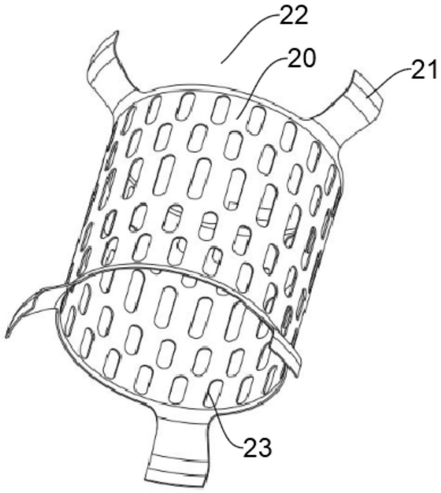
[0040] Such as figure 1 , figure 2 As shown, a box-type post-treatment mixer disclosed in this embodiment includes an outer tube 10, a mixing hole tube 20 arranged inside the outer layer tube 10, and multiple holes arranged at the front end and the rear end of the mixing hole tube 20 along the airflow direction. A set of swirl structures, each set of swirl structures includes a plurality of swirl fan blades 30 independent of each other, and each swirl fan blade 30 is separated from each other at the center of rotation. Since the swirl fan blade 30 is in the rotation process, the centrifugal force at the center is the lowest, which is the most prone to crystallization, while the edge of the swirl fan blade 30 is already in a separated state, so this embodiment uses the traditional post-processing mixer The integrated swirl fan is improved to a split swirl fan blade 30, by forming a separation at the center of each swirl fan blade 30, reducing the crystallization of urea at th...

Embodiment 2

[0044] The technical solution of this embodiment is basically the same as that of Embodiment 1, the only difference is that in this embodiment, each swirl structure is an axial swirl structure. The present application does not limit the specific structure of the swirling flow structure. In one embodiment, the swirling flow structure is an axial flow fan, and the aforementioned axial swirling flow structure is formed by the axial flow fan, and the mixed flow of exhaust gas and urea spray passes through After being guided by the axial flow fan, it flows along the axial direction of the outer tube 10 . However, the conventional vortex fan blade structure in the prior art can easily guide the airflow to the inner wall of the outer tube 10, so that the urea spray can easily crystallize on the inner wall of the outer tube 10, resulting in uneven mixing and blocking of the mixing channel by crystallization. In this embodiment, after optimizing the swirl structure to an axial swirl st...

Embodiment approach 1

[0050] In this embodiment, if Figure 4 As shown, the outer edge of each swirl fan blade 30 is provided with a first connecting portion 33 , and each swirl fan blade 30 is respectively fixed to the inner wall of the outer tube 10 through the first connecting portion 33 . Since each swirl fan blade 30 is provided independently, each swirl fan blade 30 needs to be respectively fixed on the inner wall of the outer tube 10 . In this embodiment, a first connecting portion 33 is provided on the outer edge of each swirling fan blade 30, and the first connecting portion 33 is integrally formed with the swirling fan blade 30, and the first connecting portion 33 is bent to be in line with the swirling fan. The outer arc surfaces of the blades 30 overlap, so that it is convenient to weld each swirl fan blade 30 on the inner wall of the outer tube 10 .

[0051] Preferably, the first connecting portion 33 can be formed by extending the deflector 31 in the foregoing embodiments. The defle...


PUM


Abstract

The invention relates to the technical field of automobile engines, and discloses a box-type post-treatment mixer and an engine applying the box-type post-treatment mixer, the box-type post-treatment mixer comprises an outer layer pipe, a mixing hole pipe arranged in the outer layer pipe and a plurality of sets of rotational flow structures arranged at the front end and the rear end of the mixing hole pipe in the airflow direction; each group of rotational flow structure comprises a plurality of rotational flow fan blades which are mutually independent, and the rotational flow fan blades are mutually separated at the rotating center. An integrated rotational flow fan of a traditional post-treatment mixer is improved into the split rotational flow fan blades, urea crystals at the centers of the rotational flow fan blades are reduced by forming partitions in the centers of the rotational flow fan blades, the concentration uniformity of NH3 in mixed gas in the mixer is improved, and therefore the requirements for uniform NH3 distribution of national VI box type post-treatment two-way SCR are met, and the SCR post-treatment efficiency is improved. And the box-type post-treatment emission consistency is improved.

Description

technical field [0001] The invention relates to the technical field of automobile engines, in particular to a box-type aftertreatment mixer and an engine using the same. Background technique [0002] The main measures to reduce NOx emissions of diesel vehicles include two technical routes: 1) Exhaust gas recirculation (EGR) technology: exhaust gas recirculation can reduce the maximum combustion temperature of the engine, thereby reducing NOx emissions, but high EGR rate weakens the output power of the engine and affects combustion Efficiency; 2) Selective catalytic reduction (SCR) technology. The SCR system is mainly composed of catalyst, urea supply system (UreaDosingSystem, UDS for short), control system (ECU, sensor, wiring harness, etc.) and corresponding connecting pipelines. The basic working principle of the SCR system: the exhaust gas flows out of the turbocharger and enters the exhaust pipe, and at the same time, the urea injection unit installed on the exhaust pip...

Claims


Application Information

Patent Timeline
Patent Type & Authority Applications(China)
IPC IPC(8): F01N3/20F01N3/28
CPCF01N3/2066F01N3/28F01N2610/14F01N2610/1486F01N2610/02F01N2570/14F01N2610/1453Y02A50/20Y02T10/12
Inventor 张言库
Owner WEICHAI POWER CO LTD
Why Eureka
Try Eureka