Support member, image carrier and image forming device

A technology of image carrier and supporting parts, which is applied in the direction of electric recording process applying charge pattern, equipment and instrument of electric recording process applying charge pattern, etc. Effect

Active Publication Date: 2019-10-25
FUJIFILM BUSINESS INNOVATION CORP
View PDF4 Cites 0 Cited by
  • Summary
  • Abstract
  • Description
  • Claims
  • Application Information

AI Technical Summary

Problems solved by technology

Therefore, when a supporting member having a C-shaped cross section is used, the effect of suppressing the vibration of the photosensitive drum may decrease

Method used


Image

  • Support member, image carrier and image forming device
  • Support member, image carrier and image forming device
  • Support member, image carrier and image forming device

Examples


no. 1 example

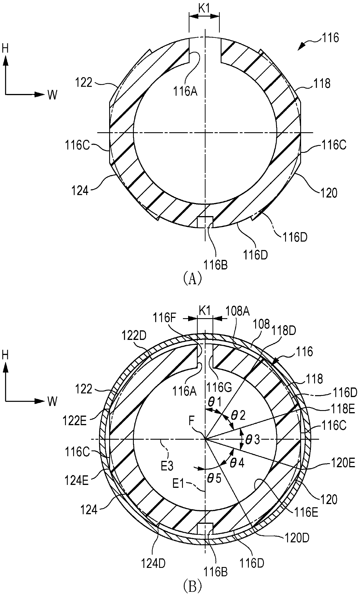
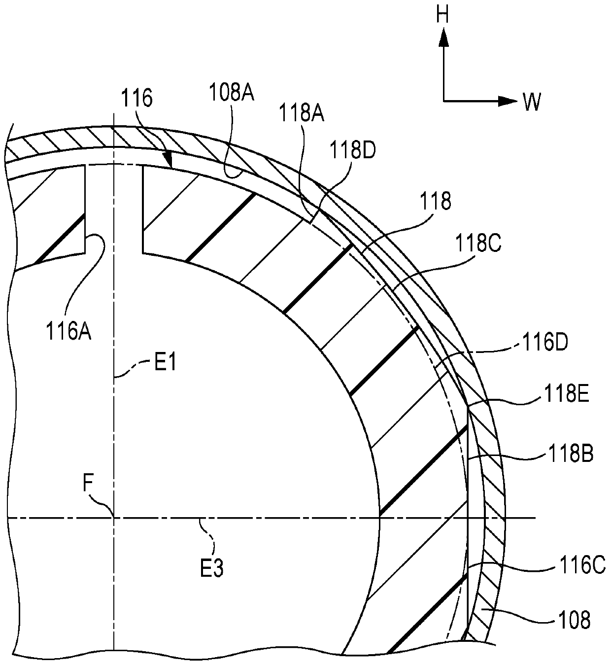
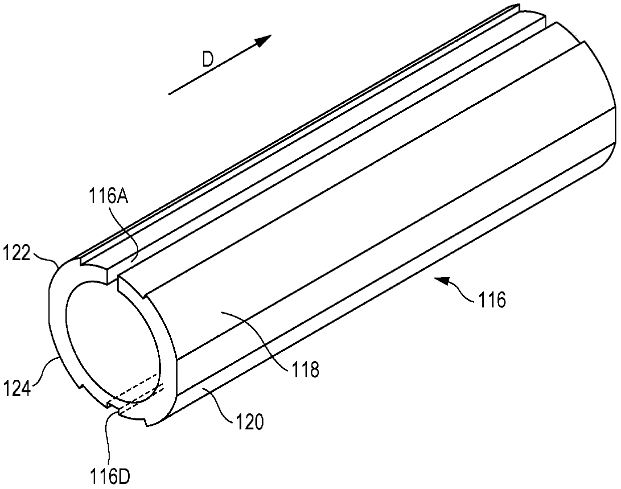
[0073] reference Picture 12 The supporting member 116 according to the first embodiment may be fitted to the cylindrical body 108 so that the supporting member 116 is supported in the central region of the cylindrical body 108 in the device depth direction.

[0074] The supporting member 116 is made of a resin material. Such as figure 1 As shown in (A) and (B) of, the support member 116 is arc-shaped and includes ends where a gap 116A is provided and opposed to each other. The gap 116A is formed in the support member 116 so as to extend in the axial direction at a specific position in the circumferential direction. In the first embodiment, the support member 116 is made of acrylonitrile-butadiene-styrene (ABS) resin. The wall thickness of the supporting member 116 is 4 mm, and the length of the supporting member 116 in the device depth direction is 100 mm.

[0075] Such as figure 1 As shown in (B), in the state where the supporting member 116 is supported in the cylindrical body...

no. 2 example

[0089] The support member 136 according to the second embodiment is described below. The difference between the support part 136 and the support part 116 will be mainly described below.

[0090] in Figure 4 In (B), the outer peripheral surface 136D of the support member 136 according to the second embodiment is represented by a chain line and a solid line, which extends in the depth direction of the device. In a state in which the support member 136 is provided in the cylindrical body 108, the outer peripheral surface 136D is a circular surface when viewed in the depth direction of the device. The outer peripheral surface 136D partially includes an imaginary surface.

[0091] In a state where the support member 136 is supported in the cylindrical body 108, when viewed in the device depth direction, the support member 136 includes a pair of flat portions 136C that are symmetrical to each other with respect to the straight line E1. Such as Figure 4 As shown in (A) and (B), the fl...

no. 3 example

[0102] The support member 156 according to the third embodiment is described below. The difference between the support part 156 and the support part 116 will be mainly described below.

[0103] in Image 6 In (B), the outer peripheral surface 156D of the support member 156 according to the third embodiment is represented by a chain line and a solid line, which extends in the depth direction of the device. In a state where the support member 156 is provided in the cylindrical body 108, when viewed in the depth direction of the device, the outer peripheral surface 156D is a circular surface, and the outer peripheral surface 156D partially includes an imaginary surface.

[0104] In a state where the support member 156 is supported in the cylindrical body 108, when viewed in the device depth direction, the support member 156 includes a pair of flat portions 156C symmetrical to each other with respect to the straight line E1. Such as Image 6 As shown in (A) and (B), the flat portion 1...


PUM


Abstract

A support member supported in a cylinder includes six or more contact portions that are in contact with an inner peripheral surface of the cylinder. The support member is arc-shaped and has a gap extending in an axial direction of the cylinder. When the support member is viewed in the axial direction, a groove is formed in the support member such that the groove and the gap are on opposite sides of a center of the cylinder, and the contact portions are symmetrical with respect to a straight line that passes through the centers of the gap and the cylinder. Of the contact portions on one side of the straight line, the farthest contact portions are separated from each other by approximately 90 degrees or more, and the adjacent contact portions are separated from each other by approximately 20 degrees or more in the circumferential direction.

Description

Technical field [0001] The present invention relates to a supporting member, an image carrier and an image forming device. Background technique [0002] The image forming apparatus described in Japanese Patent Laid-Open No. 08-54804 includes a photosensitive drum in which a sliding member is provided. The sliding member contacts the inner wall surface of the photosensitive drum in a slidable manner, and applies a predetermined pressing force to the inner wall surface. [0003] The sliding member (support member) described in Japanese Patent Laid-Open No. 08-54804 has a gap extending in the axial direction of the photosensitive drum (cylindrical body) at a specific position in the circumferential direction. The sliding member is C-shaped in cross section so that its two ends face each other. The sliding member is designed so that its outer peripheral surface is in contact with the inner peripheral surface of the photosensitive drum over the entire area of ​​the sliding member. [0...

Claims


Application Information

Patent Timeline
Patent Type & Authority Patents(China)
IPC IPC(8): G03G15/00
CPCG03G15/0216G03G15/0896G03G15/1685G03G15/751G03G15/10
Inventor 牧浦伸哉纳浩史森正裕山崎修平荒毛一志早坂知士
Owner FUJIFILM BUSINESS INNOVATION CORP
Why Eureka
Try Eureka