Fluid fillable multi-compartment bladder for flow and flood control

a multi-compartment, fluid-flowing technology, applied in the direction of dams, marine site engineering, construction, etc., can solve the problems of labor-intensive filling and stacking of sandbags, the development of civilization near rivers, oceans and lakes is especially susceptible to flooding, and the low-lying area that is geographically challenged is also susceptibl

Inactive Publication Date: 2006-05-11
BORAGGINA NICHOLAS V
View PDF16 Cites 38 Cited by
  • Summary
  • Abstract
  • Description
  • Claims
  • Application Information

AI Technical Summary

Problems solved by technology

Any development of civilization that has occurred near rivers, oceans, and lakes is especially susceptible to flooding.
In addition, any low-lying area that is geographically challenged is susceptible as well.
The filling and stacking of the sandbags is labor intensive.
Furthermore, the unstacking of the bags and the removal of the sand after the flood conditions have subsided is also labor intensive.
These procedures may also employ expensive equipment.
The use of these and other known structures are often time-consuming, labor intensive, and sometimes impractical.

Method used


Image

  • Fluid fillable multi-compartment bladder for flow and flood control
  • Fluid fillable multi-compartment bladder for flow and flood control
  • Fluid fillable multi-compartment bladder for flow and flood control

Examples


first embodiment

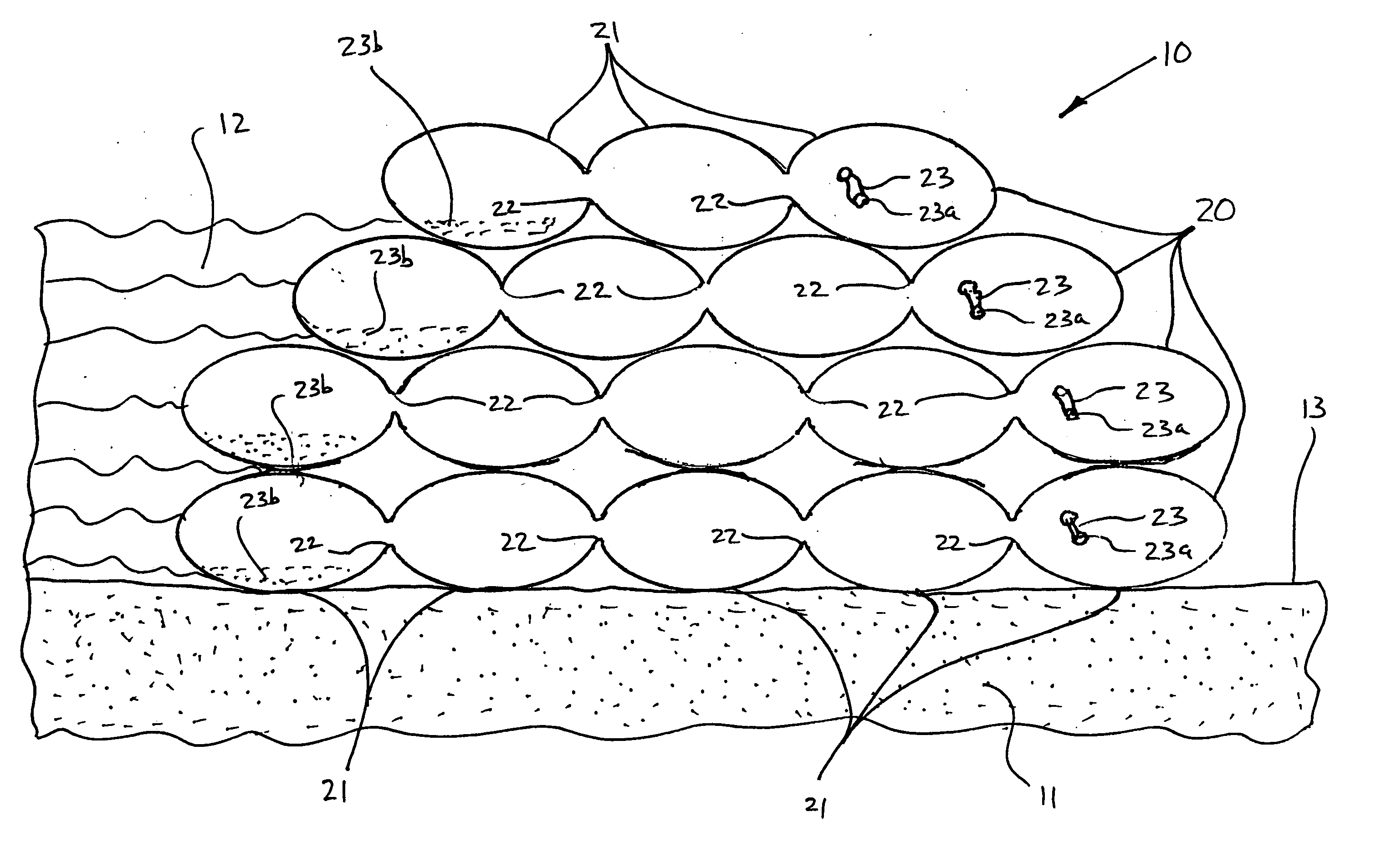
[0013] Referring now to the drawings, there is illustrated in FIG. 1 a flow and flood control system, indicated generally at 10, in accordance with this invention. In the illustrated embodiment, the system 10 is positioned on a support surface, such as an area of ground 11, to retard or prevent a fluid, such as a quantity of flood water 12, from flowing therethrough to a protected area 13. However, it will be appreciated that the system 10 of this invention can be used for any desired purpose.

[0014] The system 10 includes a plurality of bladders, each indicated generally at 20. In the illustrated embodiment, each of the bladders 20 includes a plurality of compartments 21 that extend generally horizontally relative to the ground 11. Each of the illustrated compartments 21 is generally oval in cross sectional shape. However, the compartments 21 may be formed having any other desired cross sectional shape or combination of cross sectional shapes. Each of the illustrated compartments 21...

second embodiment

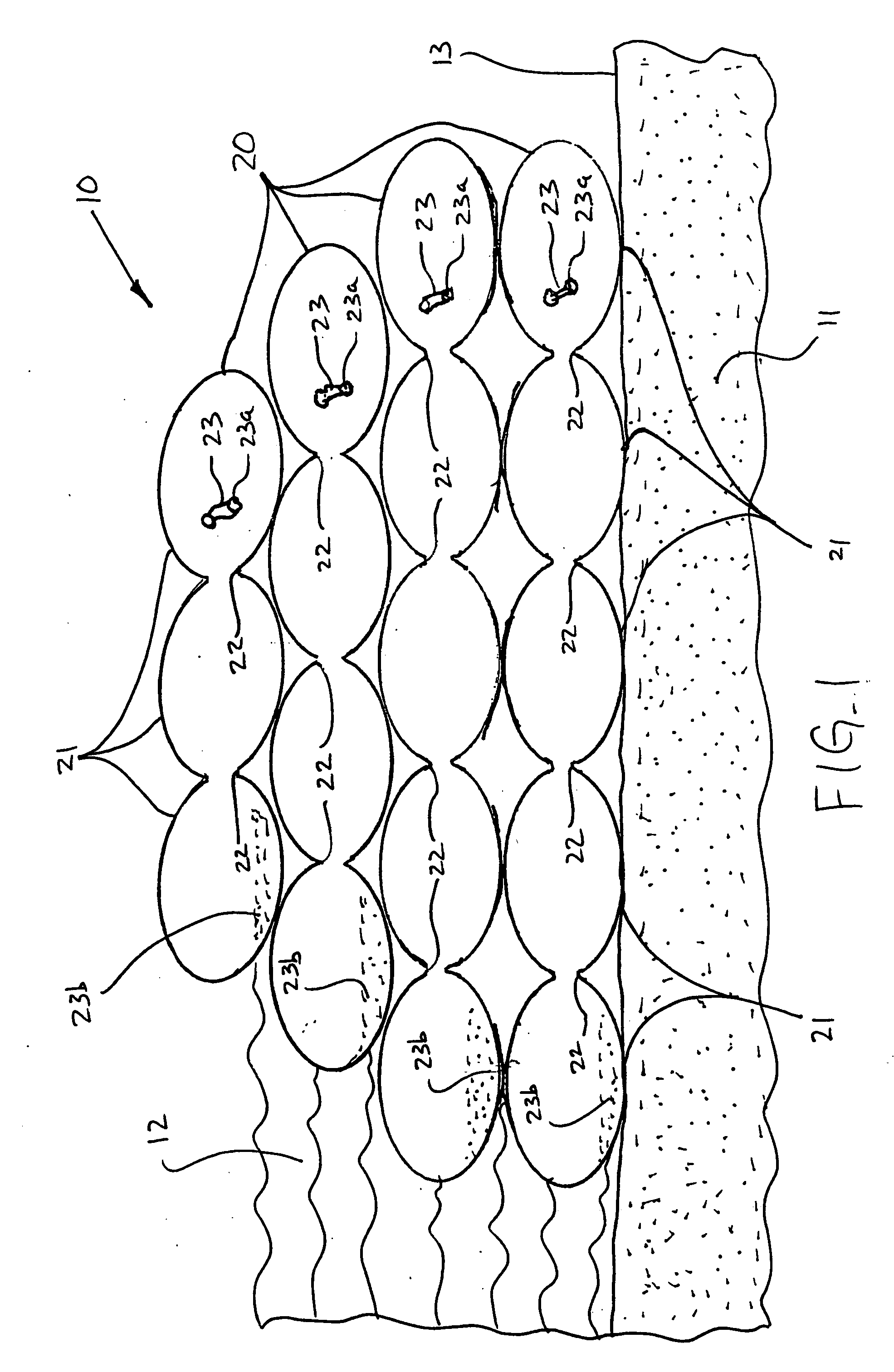
[0021] Referring now to FIG. 2, there is illustrated a flow and flood control system, indicated generally at 110, in accordance with this invention. The illustrated system 110 is a single bladder 120 that is formed in a three dimensional array that, in the illustrated embodiment, is three compartments 121 wide, five compartments 121 high, and any suitable number of compartments 121 deep. The compartments 121 can be made in varying sizes is desired. The compartments 121 communicate with one another through a plurality of passageways 122 and, therefore, can be filled from a single portal 123.

third embodiment

[0022] Referring now to FIG. 3, there is illustrated a flow and flood control system, indicated generally at 210, in accordance with this invention. The illustrated system 210 includes a pair of bladders 220, each having a plurality of spherically shaped compartments 221 that communicate with one another through respective pluralities of passageways 222 and, therefore, can each be filled from a single portal 223. The compartments 221 of the illustrated bladders 220 are staggered such that such compartments 221 mechanically nest or interlock. Additionally, fasteners 224 may be provided to secure adjacent ones of the compartments 221 together. The fasteners 224 may, for example, be embodied as conventional latch and strap arrangements, hook and loop fabrics, or any other suitable arrangement.


PUM


Abstract

A system for controlling fluid flow, such as floodwaters, includes a first bladder having a plurality of first compartments that define a plurality of first spaces therebetween and a second bladder including a plurality of second compartments that define a plurality of second spaces therebetween. At least some of the plurality of first compartments are received in the plurality of second spaces defined by the second bladder, and at least some of the plurality of second compartments are received in the plurality of first spaces defined by the second bladder. The first and second bladders are preferably formed from a water permeable material, and each of the plurality of compartments contains a quantity of a material that reacts with water or other fluid, such as a superabsorbant polymer material.

Description

CROSS-REFERENCE TO RELATED APPLICATIONS [0001] This application claims the benefit of U.S. Provisional Application No. 60 / 625,182, filed Nov. 5, 2004, the disclosure of which is incorporated herein by reference.BACKGROUND OF THE INVENTION [0002] This invention relates in general to barrier systems for controlling fluid flow. In particular, this invention relates to an improved structure for restraining the flow of water. [0003] There are many situations in which it may be desirable to control the flow of a fluid, such as spill containment or flood control. In the case of flood control, there are many areas of the world that are subject to flooding. Any development of civilization that has occurred near rivers, oceans, and lakes is especially susceptible to flooding. In addition, any low-lying area that is geographically challenged is susceptible as well. These areas include, but are not limited to, construction sites, railroads, commercial and residential structures, streets, golf c...

Claims


Application Information

Patent Timeline
Patent Type & Authority Applications(United States)
IPC IPC(8): E02B3/10
CPCE02B3/108E02B3/127
Inventor BORAGGINA, NICHOLAS V.
Owner BORAGGINA NICHOLAS V
Why Eureka
Try Eureka