Devices and arrangements for performing coherence range imaging using a common path interferometer

Active Publication Date: 2006-05-25
THE GENERAL HOSPITAL CORP
View PDF99 Cites 111 Cited by
  • Summary
  • Abstract
  • Description
  • Claims
  • Application Information

AI Technical Summary

Benefits of technology

[0011] One of the objects of the present invention is to overcome the above-described deficiencies, and provide a device and method for low-coherence ranging where reference and sample arms traverse substantially the same path. Another object of the present invention is to provide such device and method where sample and reference arms reside within the sample ar

Problems solved by technology

Path length mismatches.
The use of optical fiber based catheters in OCT is problematic due to artifacts that may occur when the catheter is bent or twisted while scanning the OCT beam on the sample.
For example, even for small bends of the catheter, the image tends to drift off of the screen.
This effect occurs because twisting or bending the optical fiber within the catheter causes a path length mismatch b

Method used


Image

  • Devices and arrangements for performing coherence range imaging using a common path interferometer
  • Devices and arrangements for performing coherence range imaging using a common path interferometer
  • Devices and arrangements for performing coherence range imaging using a common path interferometer

Examples


Embodiment Construction

[0028] Exemplary embodiments of the present invention provides a further OCT paradigm that can place the “reference arm” within the body of the catheter, thereby forming a common-path interferometer.

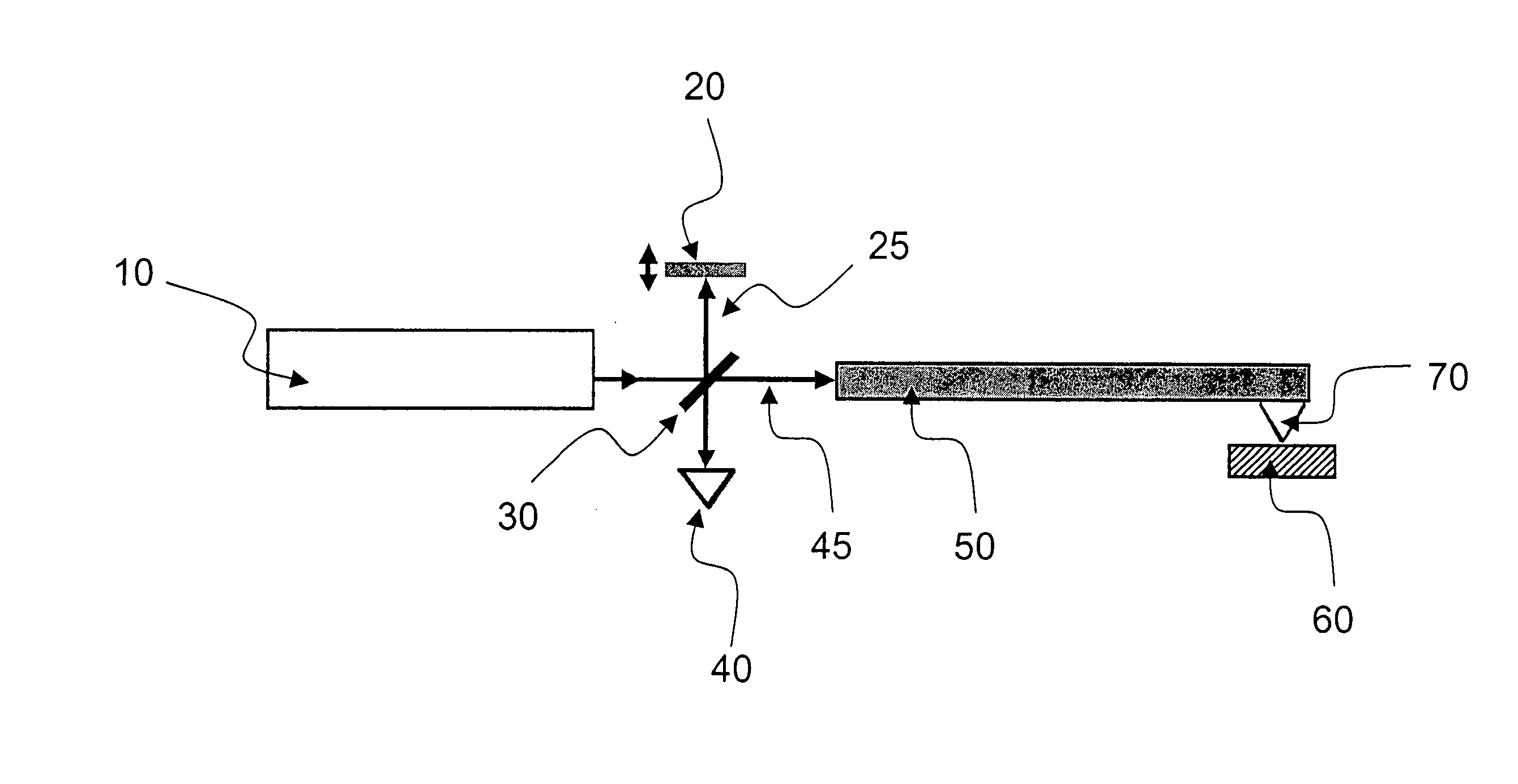
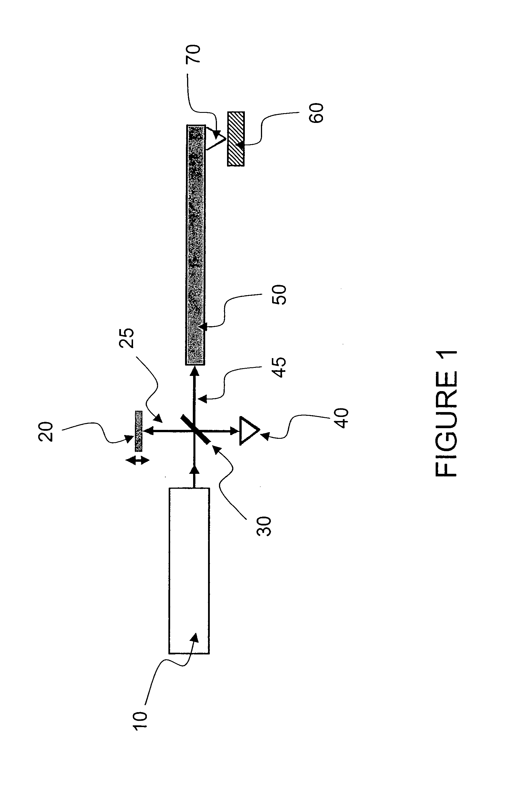
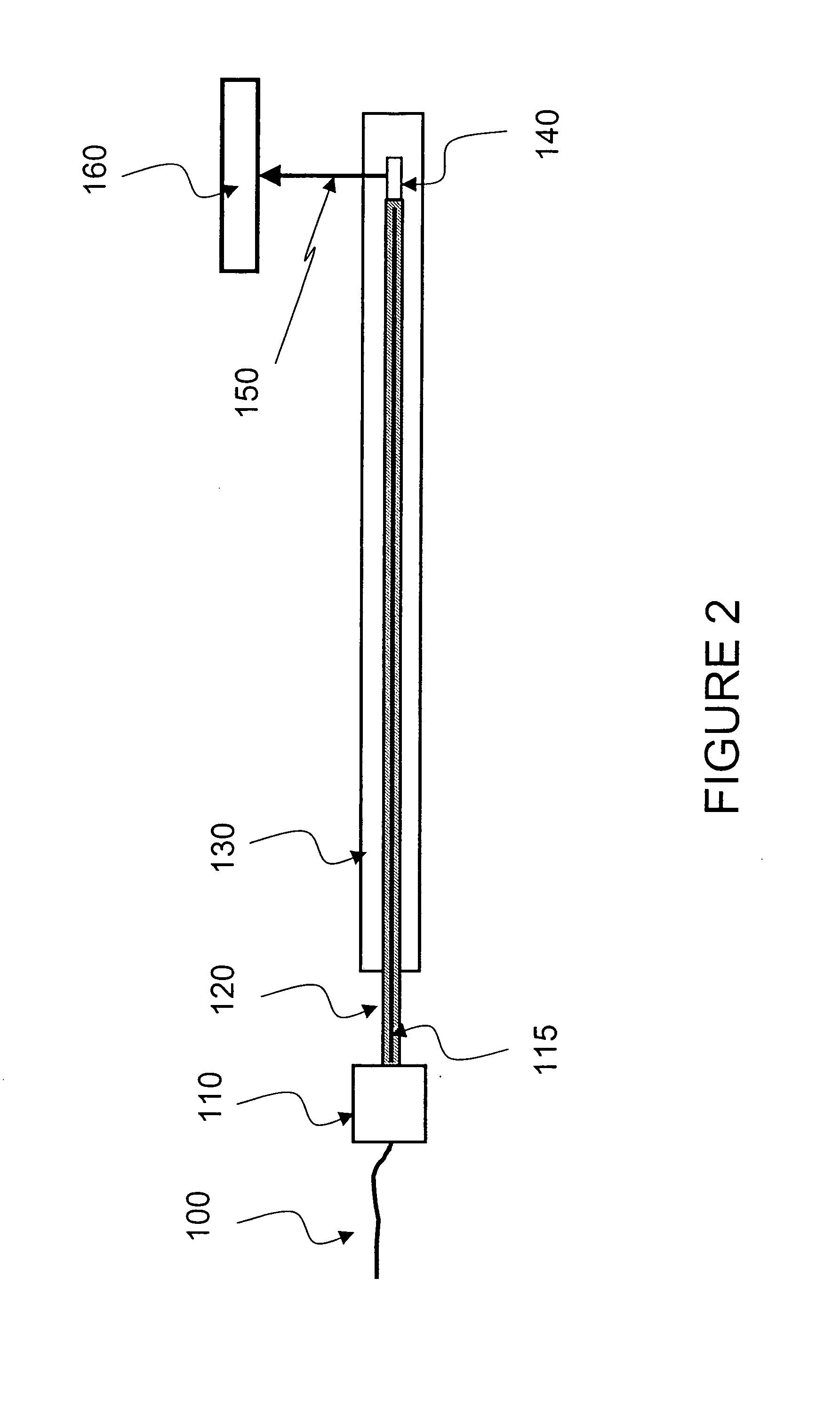
[0029] Exemplary embodiments of the system, arrangement and device capable of employing such configuration are shown in FIGS. 3 and 4. For example, a common-path interferometer may be constructed by facilitating one or more of the optical elements in the distal optics 250, 300 of the catheter to redirect some light back to the OCT system. An optical interface 307 of an object 310 as shown in FIG. 4 can redirect a fraction of light 350 back to the OCT system, and may transmit the majority of the light 320 to the sample 305, which is reflected in a path 330. Paths 330 and 350 can be combined as passes 330 through the optical element 310.

[0030] Since the both paths 330, 350 are located approximately at or near the tissue surface, the paths can become inherently matched, and would likely n...


PUM


Abstract

Devices, arrangements and apparatus adapted to propagate at least one electro-magnetic radiation are provided. In particular, a probe housing, a sample arm section and a reference arm section can be included. For example, the sample arm section can be at least partially situated within the probe housing, and configured to propagate a first portion of the electro-magnetic radiation that is intended to be forwarded to a sample. The reference arm section can be at least partially situated within the probe housing, and configured to propagate a second portion of the electro-magnetic radiation that is intended to be forwarded to a reference. In addition or as an alternative, an interferometer may be situated within the probe housing. The first and second portions may travel along substantially the same paths, and the electro-magnetic radiation can be generated by a narrowband light source that has a tunable center wavelength. Further, the first and second portions may be at least partially transmitted via at least one optical fiber. A splitting arrangement may be provided which splits the electro-magnetic radiation into the first and second portions, and positioned closer to the sample than to the source of the electro-magnetic radiation, and the first and second portions may be adapted to propagate in different directions. An apparatus may be provided that is configured to control an optical path length of the second portion.

Description

CROSS-REFERENCE TO RELATED APPLICATION(S) [0001] The present invention claims priority from U.S. patent application Ser. No. 60 / 630,964 filed on Nov. 24, 2004, the entire disclosure of which incorporated herein by reference.FIELD OF THE INVENTION [0002] The present invention relates to optical imaging, and more particularly devices and methods which are capable of performing coherence range imaging using a common path interferometer. BACKGROUND OF THE INVENTION [0003] Optical coherence tomography (“OCT”) and techniques and arrangement which are similar to derivative thereof have become promising techniques for obtaining high-resolution cross-sectional images of human tissue in vivo. One manner for conducting OCT may be based on time domain OCT scanning (“TD-OCT”). In this exemplary method, the length of the reference arm in an interferometer can be rapidly scanned over a distance corresponding to the imaging depth range. [0004]FIG. 1 shows an exemplary system which can utilize the T...

Claims


Application Information

Patent Timeline
IPC IPC(8): G01B9/02
CPCA61B5/0066A61B5/6852G01D5/35303G01N21/4795G01B9/02004G01B9/02044G01B9/02057G01B9/0205G01B9/02091G01B2290/70
Inventor TEARNEY, GUILLERMO J.BOUMA, BRETT EUGENE
Owner THE GENERAL HOSPITAL CORP
Why Eureka
Try Eureka