Fuel cell stack

a fuel cell and stack technology, applied in the field of fuel cell stacks, can solve the problems of degrading power generation performance, unable to efficiently reduce the overall size of the fuel cell stack, and unable to effectively utilize the area of the separator b>1/b> as the power generation surface, etc., to achieve the effect of maintaining the desired power generation performance and simple and economical structur

Inactive Publication Date: 2006-05-25
HONDA MOTOR CO LTD
View PDF6 Cites 44 Cited by
  • Summary
  • Abstract
  • Description
  • Claims
  • Application Information

AI Technical Summary

Benefits of technology

[0013] A main object of the present invention is to provide a fuel cell stack having a simple and economical structure in which it is possible to maintain the desired power generation performance.

Problems solved by technology

The flows of the oxygen-containing gas and the fuel gas are disturbed, and the power generation performance is degraded.
Therefore, the area of the separator 1 cannot be effectively utilized as the power generation surface.
Thus, it is not possible to efficiently reduce the overall size of the fuel cell stack.

Method used


Image

  • Fuel cell stack
  • Fuel cell stack
  • Fuel cell stack

Examples


first embodiment

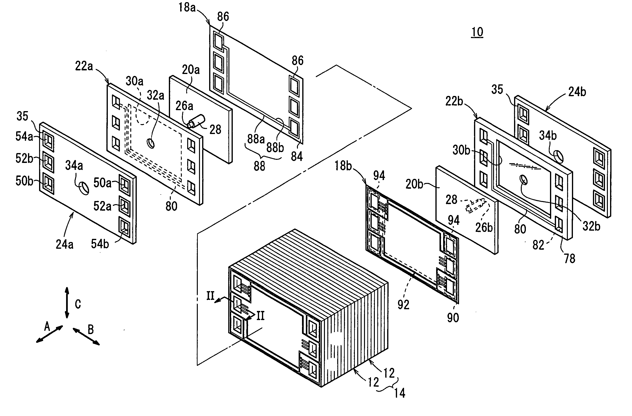
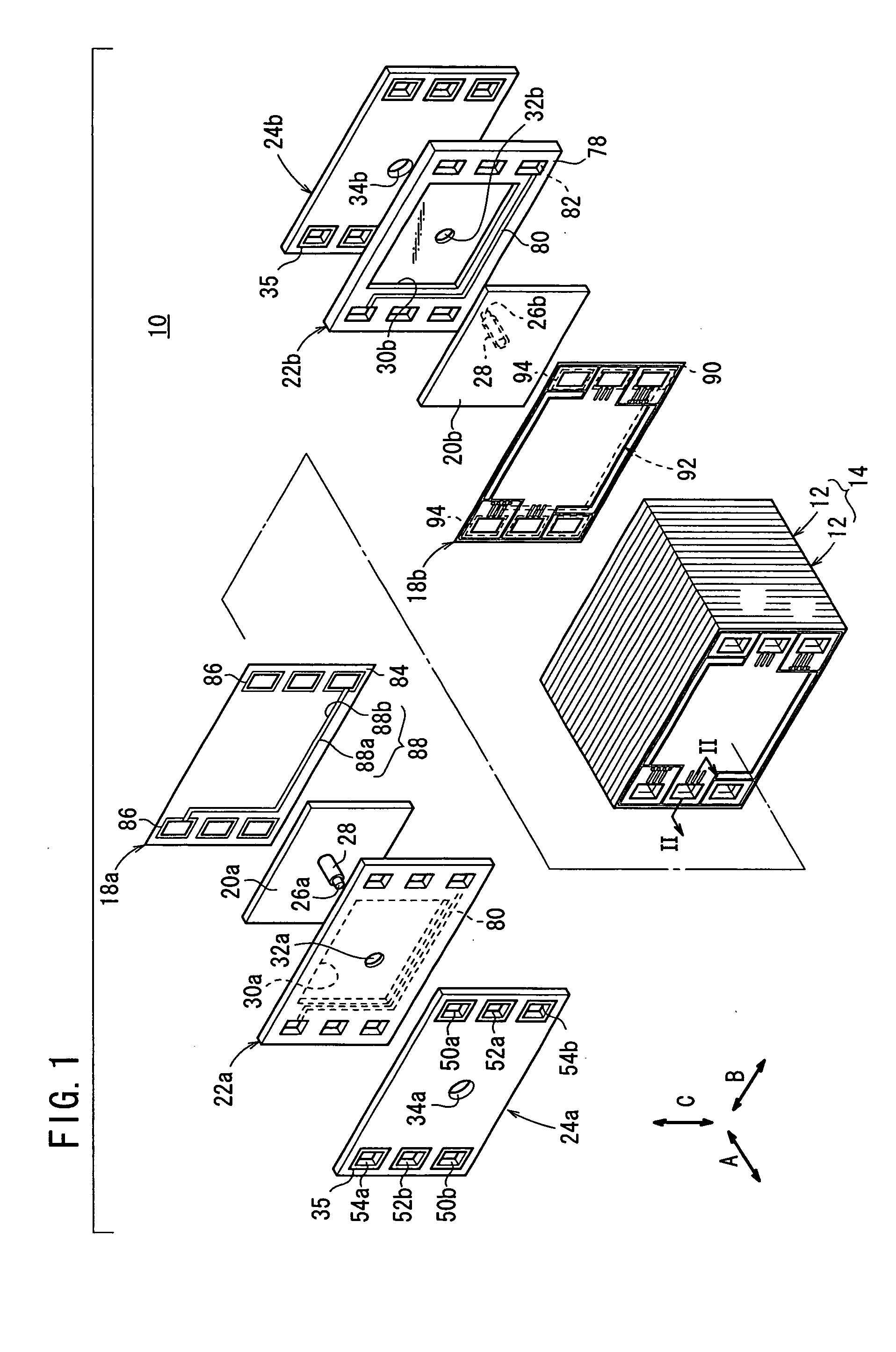
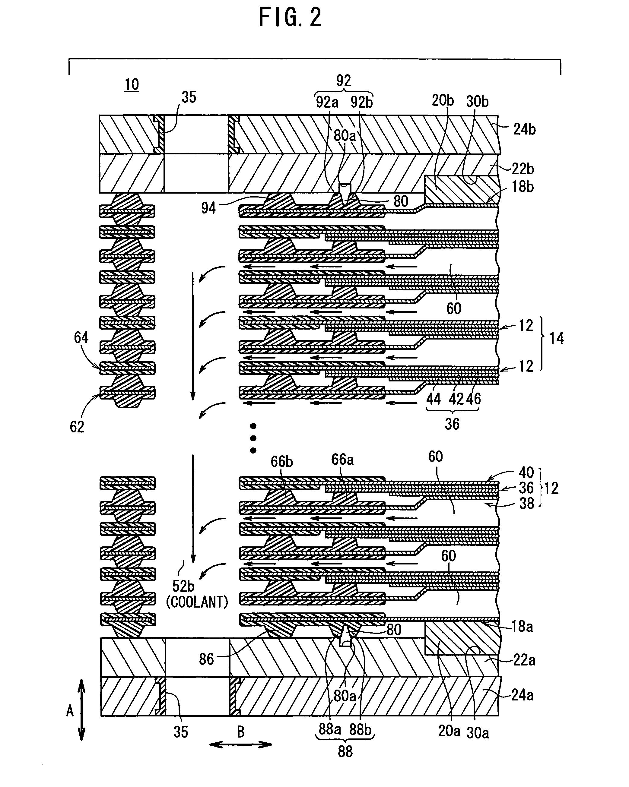
[0032]FIG. 1 is a partial exploded perspective view showing a fuel cell stack 10 according to the present invention. FIG. 2 is a cross sectional view showing the fuel cell stack 10, taken along a line II-II in FIG. 1.

[0033] The fuel cell stack 10 includes a stack body 14 formed by stacking a plurality of power generation cells 12 in a stacking direction indicated by the arrow A. At one end of the stack body 14 in the stacking direction indicated by the arrow A, an end separator 18a is provided. A terminal plate 20a is provided outside the end separator 18a. An insulating plate 22a is provided outside the terminal plate 20a. Further, an end plate 24a is provided outside the insulating plate 22a. At the other end of the stack body 14 in the stacking direction indicated by the arrow A, an end separator 18b is provided. A terminal plate 20b is provided outside the end separator 18b. An insulating plate 22b is provided outside the terminal plate 20b. Further, an end plate 24b is provided...

second embodiment

[0082] In the second embodiment, the water flowing into the fuel gas supply passage 54a is discharged through the bypass passage 104 smoothly. The bypass passage 104 is covered with the insulating seal member 108. Therefore, the condensed water flows through the insulated bypass passage 104. It is possible to prevent short circuit between the power generation cells 12, and electrical leakage to the outside of the fuel cell stack 100 through the condensed water.

[0083] Further, hydrophilic treatment is applied to the flow groove surface 104a of the bypass passage 104. Therefore, the same advantages as in the case of the first embodiment can be achieved. For example, improvement in the performance of discharging the water is achieved. It is possible to prevent the condensed water from being retained in the bypass passage 104 as much as possible, and the water is discharged from the bypass passage 104 suitably.

[0084] In the first and second embodiments, the bypass passage 80 or the byp...


PUM

PropertyMeasurementUnit
water contact angleaaaaaaaaaa
angleaaaaaaaaaa
chemicalaaaaaaaaaa

Abstract

A fuel cell stack includes a stack body, an end separator, a terminal plate, an insulating plate, and an end plate provided at one end of the stack body in a stacking direction. The insulating plate has a recess for accommodating the terminal plate. Further, the insulating plate has a bypass passage connected between a fuel gas supply passage and a fuel gas discharge passage outside the recess for discharging condensed water. An insulating seal member is provided on the end separator to cover the bypass passage. The condensed water flows through an insulated passage formed by the insulating seal member and the bypass passage.

Description

BACKGROUND OF THE INVENTION [0001] 1. Field of the Invention [0002] The present invention relates to a fuel cell stack comprising a stack body formed by stacking a plurality of electrolyte electrode assemblies and separators alternately in a stacking direction. Each of the electrolyte electrode assemblies includes a pair of electrodes, and an electrolyte interposed between the electrodes. A reactant gas supply passage and a reactant gas discharge passage for at least one reactant gas extend through the stack body in the stacking direction. The fuel cell stack further comprises terminal plates, insulating plates, and end plates provided at opposite ends of the stack body. [0003] 2. Description of the Related Art [0004] In general, a polymer electrolyte fuel cell employs a membrane electrode assembly (electrolyte electrode assembly) which includes an anode, a cathode, and an electrolyte membrane (electrolyte) interposed between the anode and the cathode. The electrolyte membrane is a ...

Claims


Application Information

Patent Timeline
Patent Type & Authority Applications(United States)
IPC IPC(8): H01M8/24H01M2/08
CPCH01M8/02H01M8/0258H01M8/0263H01M8/0273H01M8/0276H01M8/04179H01M8/04291H01M8/241H01M8/242H01M8/2465H01M2008/1095H01M2250/20Y02E60/50Y02T90/32H01M8/0267H01M8/2483Y02T90/40H01M8/0271
Inventor SUGIURA, SEIJIKONDO, JUNINAI, SHIGERUYOSHIDA, HIROMICHITANAKA, HIROYUKIMITSUTA, NAOKI
Owner HONDA MOTOR CO LTD
Why Eureka
Try Eureka