Metallic structural part joined from at least two components

Active Publication Date: 2006-06-01
MIBA SINTER AUSTRIA
View PDF9 Cites 1 Cited by
  • Summary
  • Abstract
  • Description
  • Claims
  • Application Information

AI Technical Summary

Benefits of technology

[0003] The invention is thus based on the object of providing a metallic structural part as joined from at least two components and as described above in such a way that the two components can be fixed relative to each other in the axial direction without having to build up radial tensions between the components.
[0006] Although both components can be provided in an alternating fashion with the circular latching recess and the ring segment engaging in said latching recess, especially simple constructional conditions are obtained when the annular component forms the radially projecting ring segment because generally a more favorable elastic behavior is obtained for this annular component in connection with the widening that occurs during the joining.
[0008] Since the joining of the two components is linked to an elastic deformation in the region of the ring segment of the one component as a result of the measures in accordance with the invention and the required radial forces will become effective between the components, it is recommended to form the ring segment of the one component forming the latching ring on the side facing the axial limit stop with a run-up incline, so that the sliding into each other of the two components is facilitated by a simultaneous elastic deformation of the ring segment.

Problems solved by technology

The disadvantageous aspect in this known construction is the complexity of the construction which is caused by the separate latching ring.

Method used


Image

  • Metallic structural part joined from at least two components
  • Metallic structural part joined from at least two components

Examples


Embodiment Construction

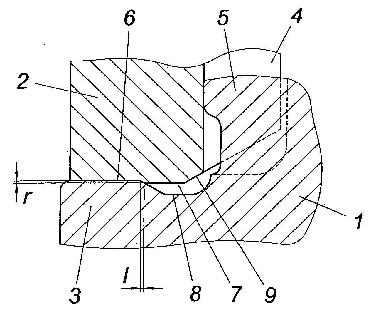
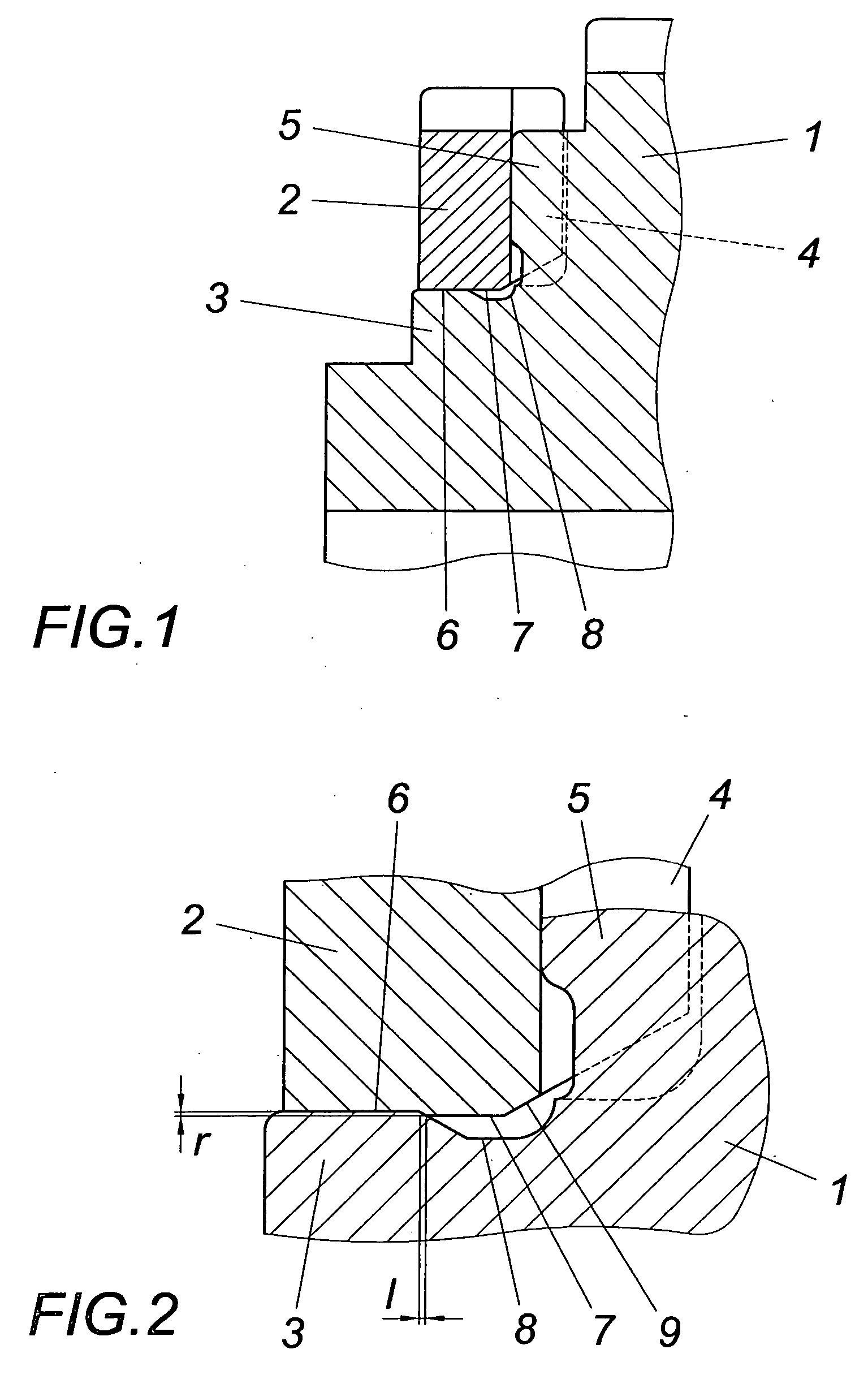
[0012] The structural part, which in the embodiment is a gearwheel, is joined of two components 1, 2, namely a toothed wheel and a clutch ring, with the component 1 forming the toothed wheel forming a hub-like nose 3 on which the annular component 2 (i.e. the clutch ring) sits. For the transmission of torque between the components 1 and 2, they comprise gearings 4, 5 on the face side, which also lead to an axial stop between the components 1 and 2. In order to prevent a withdrawal of the component 2 from the hub-like nose 3 of component 1, the annular component 2 is provided with a ring segment 7 which projects radially beyond the seating surfaces 6 between the components 1 and 2 and whose radial projecting portion r corresponds at most to the magnitude of the maximum elastic deformation of the ring segment 7 in the radial direction. The ring segment 7 cooperates with a circular latching recess 8 of the component 1, into which it engages according to the projecting portion r and thu...


PUM


Abstract

A metallic structural part is described which is joined from at least two components (1, 2), of which one component (1) comprises a hub-like nose (3) for receiving the other annular component (2) without play, which is placed on the nose (3) so as to be stopped there and is secured against axial withdrawal by a latching ring which engages in a circular latching recess (8) of one of the two components (1, 2). In order to provide simple constructional conditions it is proposed that the latching ring engaging in the latching recess (8) of the one component (1) consists of a radially projecting ring segment (7) of the other component (2) and that the radial projecting portion (r) of the ring segment (7) corresponds at most to the magnitude of the maximum elastic deformation of the ring segment (7) in the radial direction.

Description

FIELD OF THE INVENTION [0001] The invention relates to a metallic structural part which is joined from at least two components, of which one component comprises a hub-like nose for receiving the other annular component without play, which is placed on the nose so as to be stopped there and is secured against axial withdrawal by a latching ring which engages in a circular latching recess of one of the two components. DESCRIPTION OF THE PRIOR ART [0002] In order to secure two components against each other in the axial direction, namely a gearwheel and a clutch ring which is pushed onto a hub-like nose so as to be stopped there, it is known (EP 1 375 969 A2) to provide a circular groove for receiving a latching ring in the region of the hub-like nose averted from the stop, with the help of which the clutch ring is held in contact with a shoulder of the gearwheel forming a limit stop. In order to secure contact without play, the latching ring which is made of a ductile material is caulk...

Claims


Application Information

Patent Timeline
IPC IPC(8): F16H55/00F16B21/08F16H55/17
CPCF16B21/088F16H55/17Y10T74/19851Y10T403/62Y10T403/4966F16D2011/002F16D11/14
Inventor PAMMINGER, HELMUT
Owner MIBA SINTER AUSTRIA
Why Eureka
Try Eureka