Light source device and image display device

a technology of light source and image, which is applied in the direction of lighting and heating equipment, television systems, instruments, etc., can solve the problems of inefficiency in efficient utilization of light from the light source device, inability to efficiently utilize light from the light emitting part, so as to achieve the effect of reducing the extent of luminous flux, brighter illumination light, and reducing the degree of luminous flux

Inactive Publication Date: 2006-06-01
COLUMBIA PEAK VENTURES LLC
View PDF10 Cites 43 Cited by
  • Summary
  • Abstract
  • Description
  • Claims
  • Application Information

AI Technical Summary

Benefits of technology

[0020] The polarized light in the first vibrating direction that has been incident on the polarization separating part from the third light emitting part travels in the direction of the second light emitting part after passing through the polarization separating part. The light that has traveled in the direction of the second light emitting part reflects at the reflection part and travels in the direction of the polarization separating part. The polarized light in the second vibrating direction that has been incident on the polarization separating part from the third light emitting part travels in the direction of the first light emitting part after reflecting on the polarization separating part. The light that has traveled in the direction of the first light emitting part reflects at the reflection part and travels in the direction of the polarization separating part. The light from the third light emitting part, by transmission and reflection at the polarization separating part, and polarization conversion, travels in the predetermined direction. Hereby, the light from the third light emitting part can be caused to travel in the predetermined direction, and brighter illumination light can be supplied.
[0021] Further, it is preferable that: the light source device includes a first polarization separating part and a second polarization separating part; the first polarization separating part synthesizes the lights from the light emitting parts provided correspondingly to the first polarization separating part and causes the synthesized light to travel in the direction of the second polarization separating part; and the second polarization separating part synthesizes the light from the first polarization separating part and the lights from the light emitting parts provided correspondingly to the second polarization separating part and causes the synthesized light to travel in the predetermined direction. By providing respectively the light emitting parts correspondingly to the first polarization separating part and the second polarization separating part, more light emitting parts can be arranged than those in the case of using the sole polarization separating part. Further, by synthesizing the light from the first polarization separating part and the lights from the light emitting parts provided correspondingly to the second polarization separating part, extent of the luminous flux can be reduced. Hereby, the extent of the luminous flux can be reduced, and brighter illumination light can be obtained.
[0022] Further, according to another aspect of the invention, it is possible to provide an image display device which includes the above light source device, and a spatial light modulator which modulates the light from the light source device according to image signals. By providing the above light source device, the light can be supplied with high efficiency to the spatial light modulator that is an object of illumination. Hereby, it is possible to obtain an image display device which can display a bright image with high efficiency of light utilization.

Problems solved by technology

Therefore, the larger the spatial extent of the luminous flux which is incident on the spatial light modulator is, the more difficult it is to use the light from the light source device effectively.
Therefore, even in the case that the technologies disclosed in JP-A-2000-221499 and JP-A-2003-57445 are used, there is a case in which the light cannot be efficiently utilized.
Particularly, impossibility of the efficient utilization of the light from the light emitting part is a problem, because there is a case in which a bright image cannot be obtained even when plural light emitting parts are used.

Method used


Image

  • Light source device and image display device
  • Light source device and image display device
  • Light source device and image display device

Examples


embodiment 1

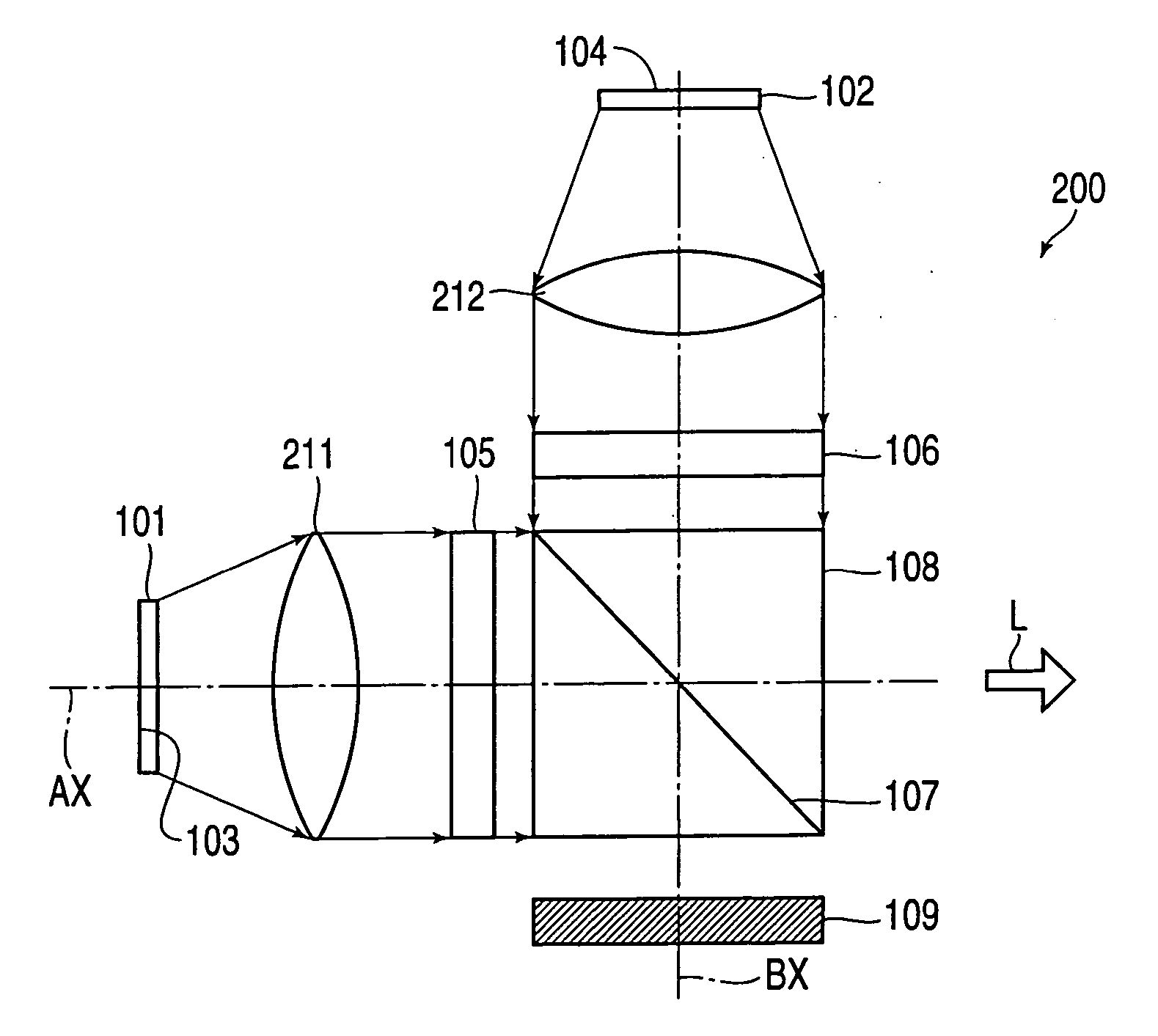
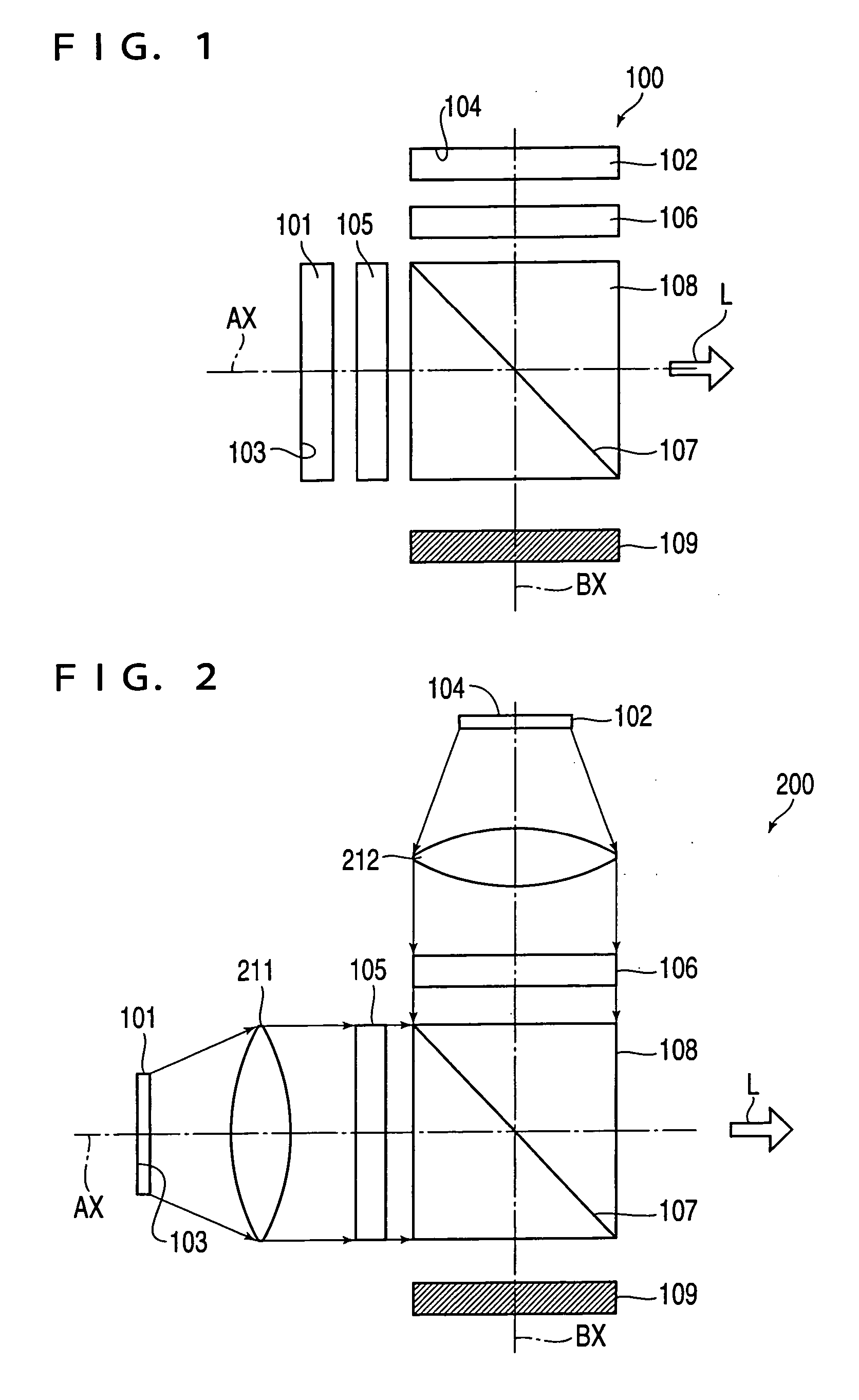
[0037]FIG. 1 shows the schematic constitution of a light source device 100 according to a first embodiment of the invention. The light source device 100 includes a LED 101 that is a first light emitting part, and a LED 102 that is a second light emitting part. The LED's 101 and 102 are surface-emitting light sources which emit light mainly from a surface of a chip. The LED's 101 and 102 supply the light in the direction of a polarization beam splitter 108. The polarization beam splitter 108 is a structure having the shape of rectangular solid, which is formed by laminating two prisms. Between the two prisms of the polarization beam splitter 108, a polarization film 107 is formed.

[0038] The polarization film 107 is a polarization separating part, which transmits polarized light in a first vibrating direction of the lights from the LED's 101 and 102, and reflects polarized light in a second vibrating direction, thereby to separate the lights from the LED's 101 and 102 into the polari...

embodiment 2

[0059]FIG. 6 shows the schematic constitution of a light source device 600 according to a second embodiment of the invention. The light source device 600 is characterized by including, in addition to a LED 101 that is a first light emitting part and a LED 102 that is a second light emitting part, a LED 603 that is a third light emitting part. The LED 603 is provided on the opposite side to the side where the LED 102 is provided, of a polarization beam splitter 108. The LED 603, similarly to the LED 102, is arranged with an axis BX as a center. The LED 603 includes a reflection part 604 that is a metallic electrode. Further, between the LED 603 and the polarization beam splitter 108, a λ / 4 phase plate is not provided.

[0060] The LED 603 supplies light including p-polarized light and s-polarized light. Of the lights that have been incident on the polarization beam splitter 108 from the LED 603, the p-polarized light passes through a polarization film 107, and thereafter travels in the...

embodiment 3

[0064]FIG. 8 shows the schematic constitution of a light source device 800 according to a third embodiment. The light source device 800 is characterized by including a polarization beam splitter108 having a polarization film 107 that is a first polarization separating part, and a polarization beam splitter 808 having a polarization film 807 that is a second polarization separating part. The polarization film 107 transmits p-polarized light, and reflects s-polarized light, while the polarization film 807 transmits the s-polarized light that is polarization light in the second vibrating direction, and reflects the p-polarized light that is polarization light in the first vibrating direction.

[0065] LED's 101, 102 and 603 are provided, correspondingly to the polarization beam splitter 108, around the polarization beam splitter 108. The constitution around the polarization beam splitter 108 is similar to that of the light source device 600 shown in FIG. 6. In the constitution of the lig...


PUM


Abstract

A light source device includes at least two light emitting parts which emit light; and a polarization separating part which transmits polarized light in a first vibrating direction of the lights from the light emitting part, and reflects polarized light in a second vibrating direction nearly orthogonal to the first vibrating direction, thereby to separate the lights from the light emitting part into the polarized light in the first vibrating direction and the polarized light in the second vibrating direction. Herein, the light emitting part includes a reflection part which reflects light that travels toward the light emitting part from the polarization separating part, in the direction of the polarization separating part. The polarization separating part synthesizes the polarized light in the first vibrating direction that has passed through the polarization separating part, and the polarized light in the second vibrating direction that has reflected on the polarization separating part, thereby to cause the synthesized light to travel in a predetermined direction.

Description

[0001] The present application claims priority to Japanese Patent Application No. 2004-348234 filed Dec. 1, 2004, which is hereby expressly incorporated by reference herein in its entirety. BACKGROUND [0002] 1. Technical Field [0003] The present invention relates to a light source device and an image display device, and particularly to technology of a light source device used in combination with a spatial light modulator. [0004] 2. Related Art [0005] Recently, it has been proposed that a solid light emitting element is used in a light source device of a projector. A light emitting diode (hereinafter referred to as “LED”) that is the solid light emitting element is characterized by being ultra small, ultra light, and long in life. Further, the LED for large output is in a remarkably advanced stage of development and improvement, so that application of the LED to use for illumination is enlarging. Therefore, it is expected that the LED is used as a light source of a projector, and par...

Claims


Application Information

Patent Timeline
Patent Type & Authority Applications(United States)
IPC IPC(8): F21V9/14
CPCG03B33/12H04N9/315H04N9/3197G03B21/2073H04N5/74
Inventor SAKATA, HIDEFUMITAKEDA, TAKASHIYONEKUBO, MASATOSHIARUGA, SUSUMU
Owner COLUMBIA PEAK VENTURES LLC
Why Eureka
Try Eureka