Steam trap monitoring

a technology of steam traps and steam traps, applied in the field of steam trap monitoring, can solve the problems of reducing the efficiency of the steam system and losing valuable energy

Active Publication Date: 2006-06-08
ARMSTRONG INT INC
View PDF13 Cites 33 Cited by
  • Summary
  • Abstract
  • Description
  • Claims
  • Application Information

AI Technical Summary

Benefits of technology

[0009] One particular aspect of the invention relates to a method of monitoring the status of a steam trap. The method includes sensing a process condition of the steam trap by taking multiple readings of one or more stream trap parameters, processing the multiple readings using an algorithm in a processor mounted in a steam trap monitor positioned in the vicinity of the steam trap, and transmitting a signal, based upon the processed multiple readings, indicative of the process condition of the one or more steam trap parameters.

Problems solved by technology

If steam is allowed to pass through the steam trap into the condensate return line, the result is a loss of valuable energy and a reduction in the efficiency of the steam system.

Method used


Image

  • Steam trap monitoring
  • Steam trap monitoring
  • Steam trap monitoring

Examples


Embodiment Construction

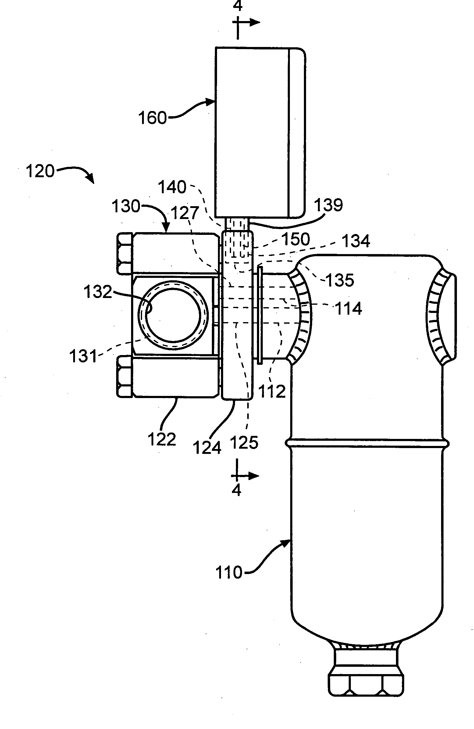
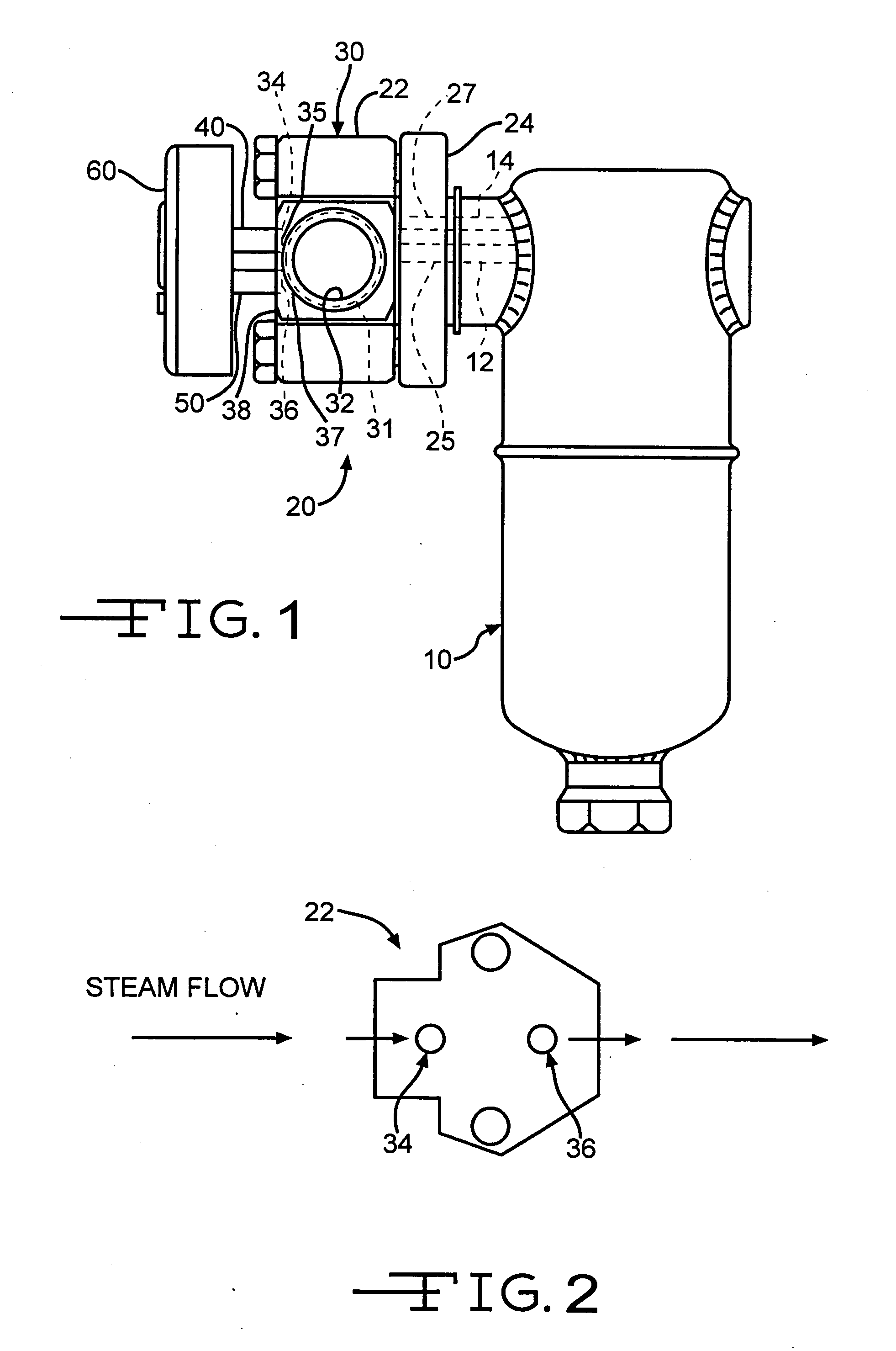
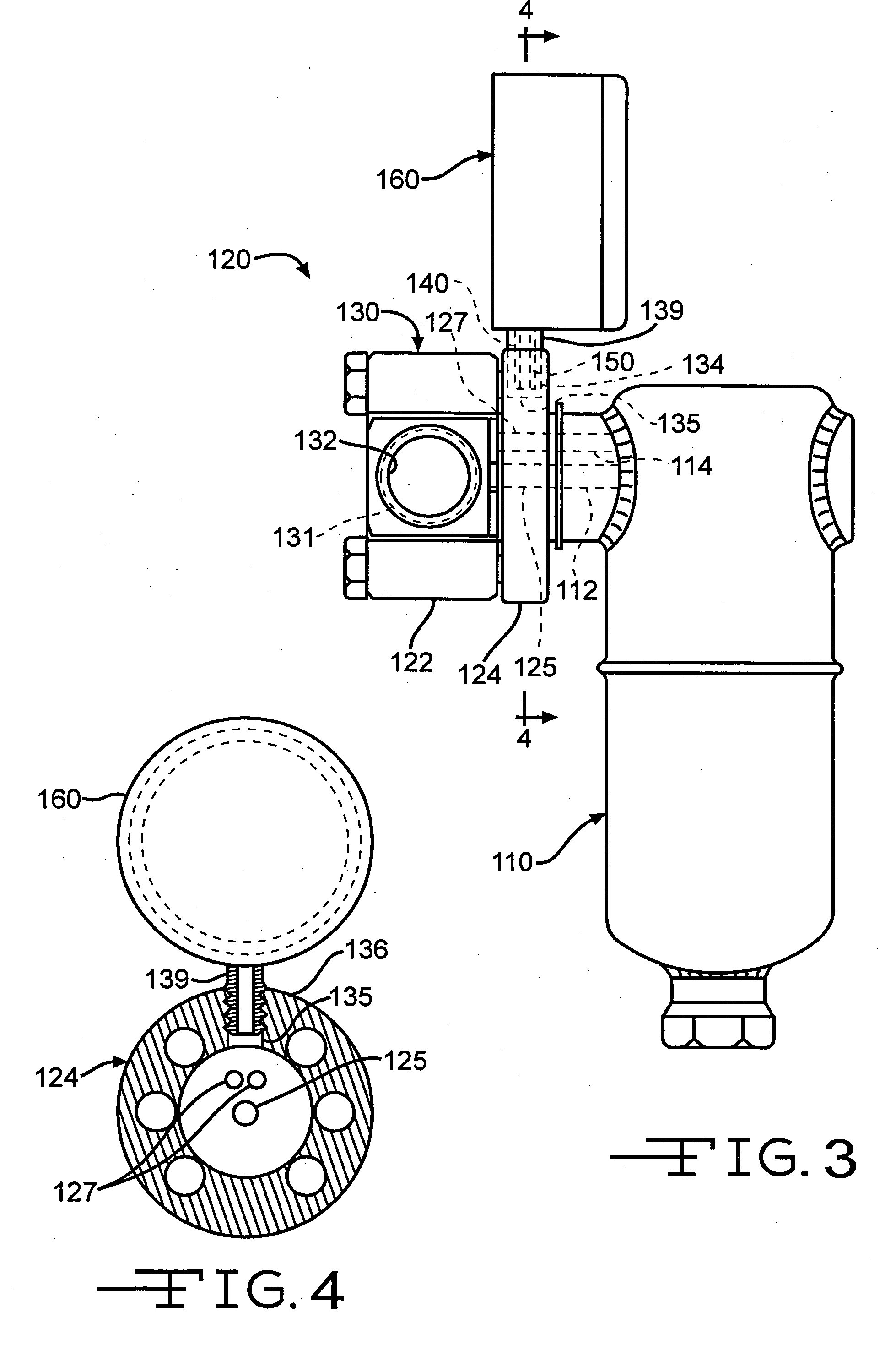
[0028] Steam traps are automatic mechanical valves that discharge condensate (water) from a steam system. In a live steam system, if a steam trap fails to function properly, there are two possible failures: 1) failed “open”, where an automatic valve in the steam trap is continuously in the open condition allowing condensate and live steam to exit the system; or, 2) failed “closed” where the trap retains all the condensate in the system and sends such condensate back into the steam system, thereby reducing the efficiencies of the steam system and possibly damaging the process equipment.

[0029] As shown in FIG. 1, one type of steam trap is generally indicated at 10. The depicted steam trap 10 is generally conventional and well known in the art, although it is to be understood that the present invention may be used with other types of steam traps. The steam trap 10 is connected to a live steam line (not shown) which supplies steam into the steam trap 10. The steam trap 10 is also conne...


PUM


Abstract

An apparatus and method for monitoring the status of a steam trap include a device for sensing a process condition of the steam trap and a device for processing the sensed condition. The apparatus can include a processor positioned on a steam trap. The connection of the monitoring device to the steam trap can be to the trap itself or to an adjacent pipe or other apparatus.

Description

RELATED APPLICATIONS [0001] This application is a Continuation-In-Part application of U.S. patent application Ser. No. 11 / 006,789, filed Dec. 8, 2004, and entitled REMOTE MONITOR FOR STEAM TRAPS.TECHNICAL FIELD AND INDUSTRIAL APPLICABILITY OF THE INVENTION [0002] The present invention relates in general to steam systems including steam traps and to steam trap monitoring. BACKGROUND OF THE INVENTION [0003] Steam traps are items of equipment common in factories, refineries and other industrial or commercial facilities. Steam traps are installed in steam lines and act to separate (remove) condensed steam, or “condensate”, from the steam without allowing the steam to escape. The separated condensate is then typically recycled back through condensate return lines to the boiler for conversion back to steam. To be effectively operating, the steam trap must generally prevent steam from escaping past the steam trap and entering the condensate return lines. If steam is allowed to pass through...

Claims


Application Information

Patent Timeline
Patent Type & Authority Applications(United States)
IPC IPC(8): G05D23/02G01M99/00
CPCF16T1/48Y10T137/3028Y10T137/8158
Inventor ARMSTRONG, DAVID M.CHESKATY, REXHORTON, WILLIAM R.GAINES, MICHAEL H.HELLMAN, MICHAEL P.GRUBKA, LAWRENCE J.
Owner ARMSTRONG INT INC
Why Eureka
Try Eureka