
Extraction device and wear ring for a rotatable tool

a technology of extraction device and rotatable tool, which is applied in the direction of cutting machines, slitting machines, earth drilling and mining, etc., can solve the problems of not being able to have a wear ring, and the forward surface of the tool holder to become worn away

Inactive Publication Date: 2006-06-15
THE SOLLAMI COMPANY
View PDF13 Cites 56 Cited by
  • Summary
  • Abstract
  • Description
  • Claims
  • Application Information

AI Technical Summary

Benefits of technology

[0007] A wear ring for use with the tool has planar forward and rearward surfaces and an inner opening sized to receive the shank of the tool. The periphery of the wear ring has a pair of opposing parallel planar surfaces and the distance between the planar surfaces is less than the first dimension and less than the second dimension. Accordingly, when the shank of the tool is first inserted through the central opening of the wear ring and then received into the bore of ...

Problems solved by technology

A tool in a machine may undergo 50,000 rotations or more during a single work day, and the rotation of the rearwardly directed flange against the forward surface of the tool holder will over time cause the forward surface of the tool holder to become worn away.
There are circumstances, however, when it is not desirable to have a wear ring, the outer diameter of which is larger than the diameter of the radial flange of the tool.

Method used


Image

  • Extraction device and wear ring for a rotatable tool
  • Extraction device and wear ring for a rotatable tool
  • Extraction device and wear ring for a rotatable tool

Examples


Embodiment Construction

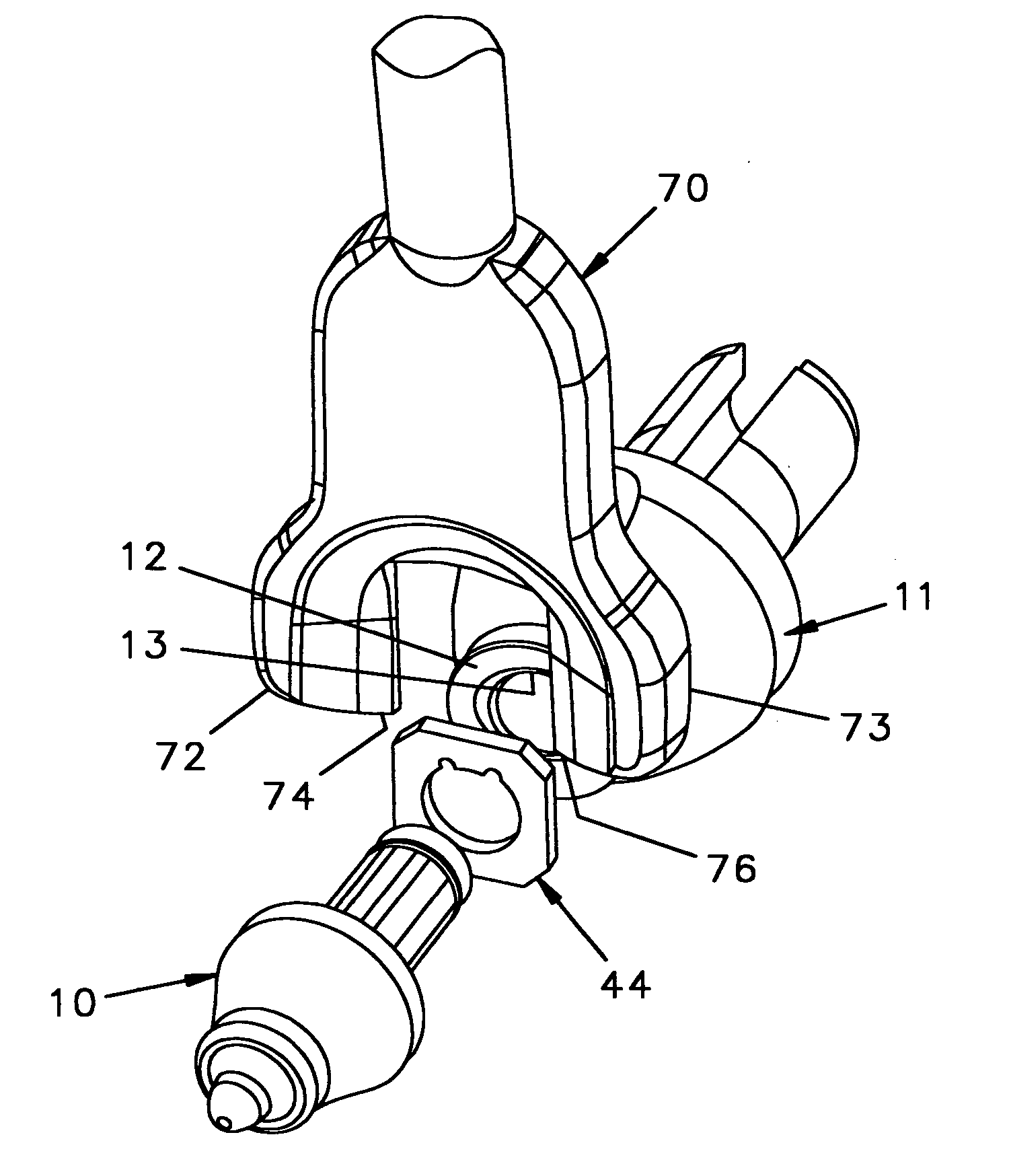
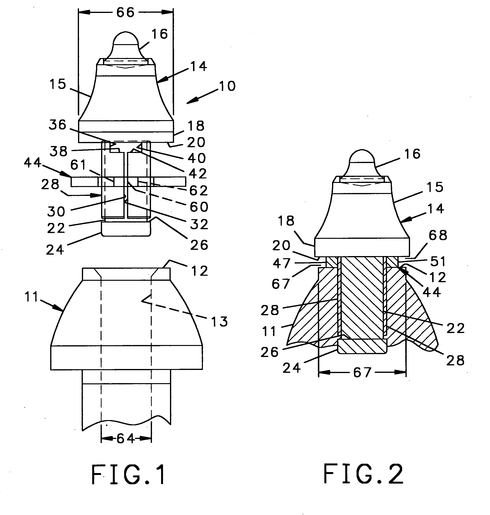
[0022] Referring to FIGS. 1 and 2, a tool 10 is suitable for being rotatably mounted in a tool holder 11 having a planar forward surface 12 and a bore 13, the axis of which is perpendicular to the forward surface 12. The tool holder 11 may be mounted directly to the drum or wheel of the machine or may be a quick-change holder as depicted. The tool 10 includes a tool body 14 having a tapered forward cutting portion 15 at the forward end of which is a seat into which is brazed a hardened cutting tip 16. The cutting portion 15 flares outwardly near its rearward end to a flange 18 having a generally planar annular rearward surface 20. Extending axially rearwardly from the center of the annular rearward surface 20 is a cylindrical shank 22 having an enlarged hub 24 at the distal end thereof. The hub 24 forms a shoulder 26, and fitted forwardly of the shoulder 26 is a compressible sleeve 28 made of a suitable spring steel.

[0023] The compressible sleeve 28 generally defines a hollow cylin...


PUM


Abstract

A tool has a tapered forward cutting end behind which is a cylindrical shank. A rearwardly facing annular flange separates the forward cutting end from the shank. The shank is received in a tool holder having a planar forward surface, and fitted around the shank of the tool is an annular wear ring. The outer diameter of the wear ring is less than the outer diameter of the radial flange and less than the diameter of the forward end of the tool holder. The thickness of the wear ring forms a gap on opposite sides of the wear ring between a portion of the tool holder and a portion of the radial flange of the tool. Spaced apart prongs of an extraction tool can be fitted into the gaps to extract the tool from the tool holder.

Description

[0001] The present invention relates to rotatable tools used in machines to cut hard surfaces and to an improved wear ring between the tool and the tool holder adapted to receive an extraction device for extracting the tool from the tool holder. BACKGROUND OF THE INVENTION [0002] Machines for cutting hard surfaces such as used in the trenching and mining industries and for highway cold planning to remove the upper surface of concrete and asphalt pavement, employ tools fitted into tool holders on a rotatable wheel or drum. The tools have a tapered forward cutting end and axially behind the cutting end is a cylindrical shank that rotatably fits within a complementarily shaped bore in the tool holder. Such rotatable tools have an annular rearwardly directed flange between the forward cutting end and the shank that contacts the forward surface of the tool holder. The shank is retained in the bore of the tool holder by a sleeve made of spring steel so as to be compressible and has an uns...

Claims


Application Information

Patent Timeline
IPC IPC(8): E21C25/10
CPCE21C35/18E21C2035/1826E21C35/188
Inventor SOLLAMI, PHILLIP A.
Owner THE SOLLAMI COMPANY
Features
  • Generate Ideas
  • Intellectual Property
  • Life Sciences
  • Materials
  • Tech Scout
  • Unparalleled Data Quality
  • Higher Quality Content
  • 60% Fewer Hallucinations
Learn More