Driving mechanism, driving system, anti-shake unit, and image sensing apparatus

a technology of anti-shake unit and driving mechanism, which is applied in the direction of television system, camera body details, instruments, etc., can solve the problems of increasing the thickness of the mechanism, unable to provide a miniaturized and lightweight mechanism, and unable to perform appropriate shake correction to cancel such a movemen

Inactive Publication Date: 2006-06-22
KONICA MINOLTA PHOTO IMAGING
View PDF3 Cites 71 Cited by
  • Summary
  • Abstract
  • Description
  • Claims
  • Application Information

AI Technical Summary

Benefits of technology

[0010] It is another object of the present invention to provide a driving mechanism and a driving system which can execute driving in θ-direction, which is a direction of rotating a movable base member around an axis of rotation thereof as well as driving in x-axis direction and driving in y-axis direction, along which parallel movements of the movable base member are executed.
[0011] It is still another object of the present invention to provide a compact image sensing apparatus which is equipped with an anti-shake mechanism of moving an image sensor in a rolling direction, as well as in pitch and yaw directions.

Problems solved by technology

Therefore, if an external force accompanying rotation is exerted to the camera, appropriate shake correction to cancel such a movement cannot be performed.
Since this arrangement requires two driving systems for shake correction, the arrangement fails to provide a miniaturized and lightweight mechanism.
Such an arrangement may increase the thickness of the mechanism, and may increase the weight thereof by the weight corresponding to the increased number of base members.

Method used


Image

  • Driving mechanism, driving system, anti-shake unit, and image sensing apparatus
  • Driving mechanism, driving system, anti-shake unit, and image sensing apparatus
  • Driving mechanism, driving system, anti-shake unit, and image sensing apparatus

Examples


Embodiment Construction

[0045] A preferred embodiment of the present invention will be conceptually described with reference to FIGS. 1 to 5B.

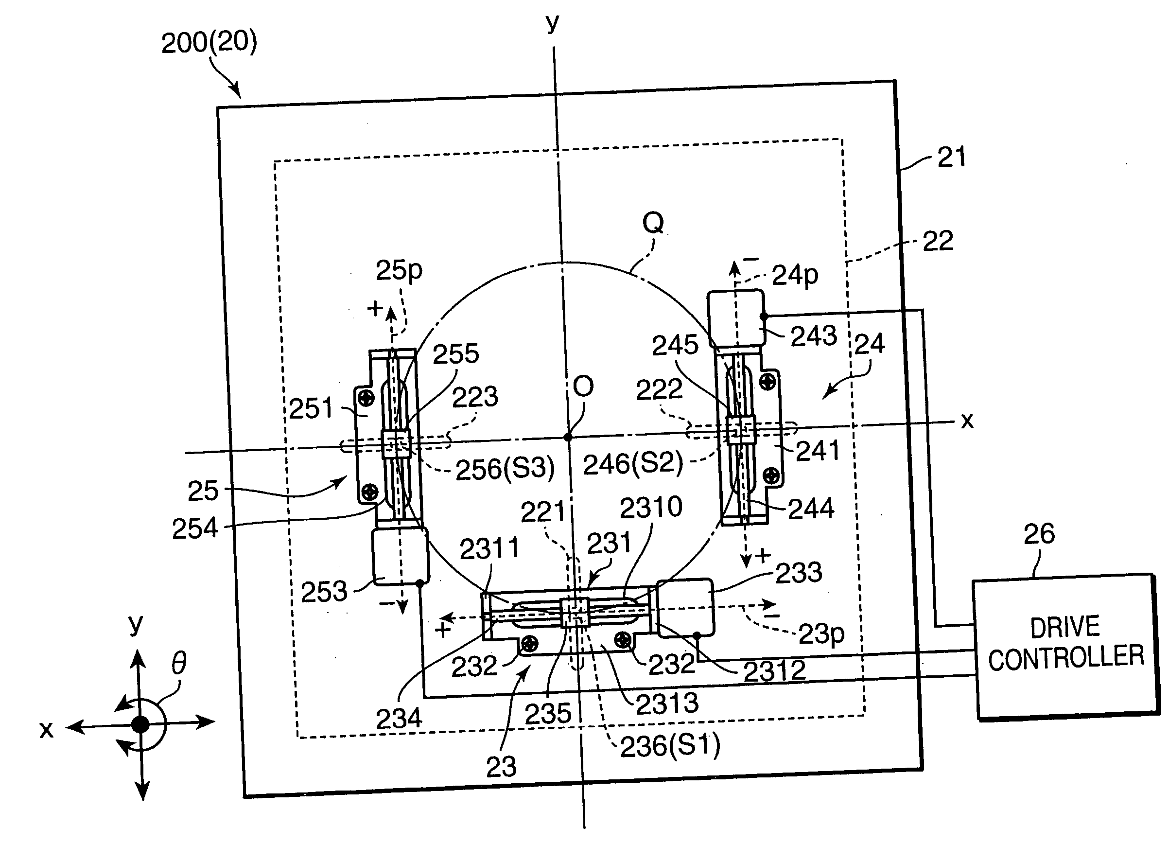
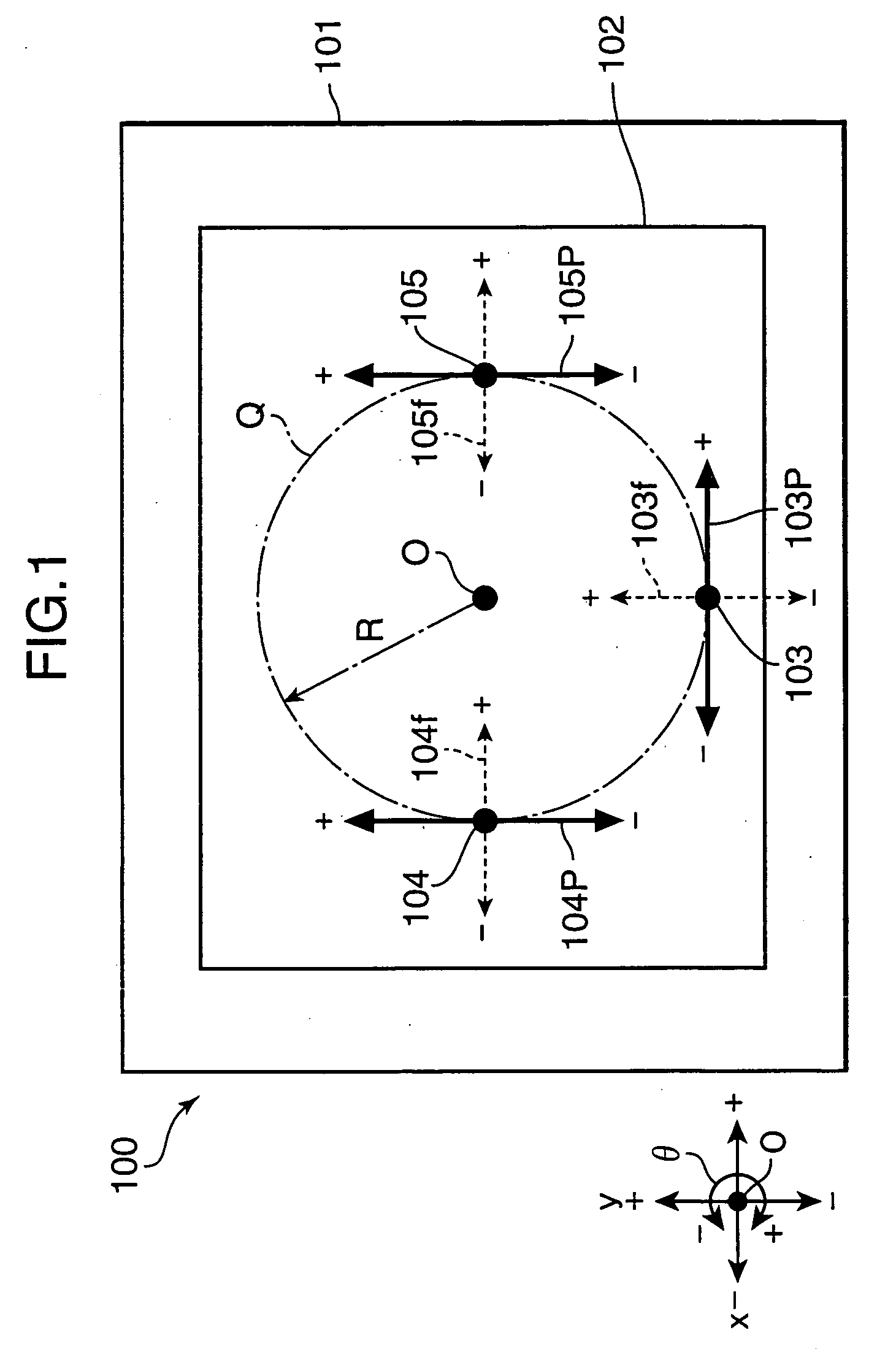
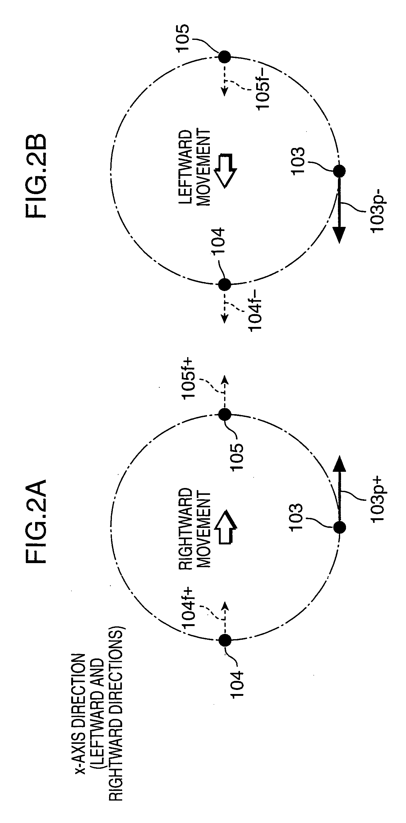
[0046] A driving mechanism embodying the invention includes a fixed base member, a movable base member movable relative to the fixed base member, and at least three driving devices. Each driving device has an operating part which is moved linearly. The three driving devices are loaded on either one of the fixed base member and the movable base member, at least three operated parts being formed on the other one of the fixed base member and the movable base member where the driving devices are not loaded to receive driving forces from the operating parts of the driving devices, respectively.

[0047] The operated parts each has a moving guide part extending in a direction of a guide axis orthogonal to a linear driving axis along which the corresponding operating part of the driving device is moved. The operating parts are guided in the respective corresponding moving gu...


PUM


Abstract

A driving mechanism includes: a fixed base member; a movable base member which is moved relative to the fixed base member; and at least three driving devices each having an operating part which is moved linearly, wherein the three driving devices are loaded on either one of the fixed base member and the movable base member, at least three operated parts are formed on the other one of the fixed base member and the movable base member where the driving devices are not loaded, driving forces from the operating parts of the driving devices are acted on the at least three operated parts, respectively. The operated parts each has a moving guide part extending in a direction of a guide axis orthogonal a linear driving axis along which the corresponding operating part of the driving device is moved. The operating parts are guided in the respective corresponding moving guide parts to cause relative rotation of one of the movable base member and the fixed base member against the other. At least one of the linear driving axes extends in a first direction, the other linear driving axis extends in a second direction orthogonal to the first direction, and the respective linear driving axes extend in tangential directions of a circle having an arbitrary point on the movable base member or the fixed base member as a center point. The respective guide axes extend in radial directions with respect to the center point

Description

[0001] This application is based on Japanese Patent Application No. 2004-365894 filed on Dec. 17, 2004, the contents of which are hereby incorporated by reference. BACKGROUND OF THE INVENTION [0002] 1. Field of the Invention [0003] The present invention relates to a driving mechanism and a driving system that enable to move a movable base member relative to a fixed base member in its rotating direction, as well as in two axis directions, and to an anti-shake unit particularly adapted for correcting shake in a digital still camera, a digital video camera, or a like apparatus incorporated with the driving mechanism and the driving system, and to an image sensing apparatus loaded with the anti-shake unit. [0004] 2. Description of the Related Art [0005] In image sensing apparatuses such as a digital still camera and a digital video camera, there is known an anti-shake mechanism of swinging an image sensor such as a CCD (charge coupled device) sensor, as disclosed in Japanese Unexamined ...

Claims


Application Information

Patent Timeline
Patent Type & Authority Applications(United States)
IPC IPC(8): G03B17/00
CPCH04N5/2253H04N5/2254H04N5/23248H04N5/23287H04N23/54H04N23/55H04N23/68H04N23/687H04N23/631
Inventor TERAMOTO, TOUGO
Owner KONICA MINOLTA PHOTO IMAGING
Why Eureka
Try Eureka