Bone fixation system

a bone fixation system and bone technology, applied in the field of bone fixation system, can solve the problems of large plate volume, adversely affecting intra-operative and post-operative viewing of the associate area of the spine, and conflicting requirements of spinal stability and system reliability over an extended period of us

Active Publication Date: 2006-07-06
ZIMMER BIOMET SPINE INC
View PDF99 Cites 129 Cited by
  • Summary
  • Abstract
  • Description
  • Claims
  • Application Information

AI Technical Summary

Benefits of technology

[0009] The present teachings also provide a method of surgically repairing bone with a fixation plate having at least one fixation hole. The method includes providing at least one fastener having a shank and a coupler, the shank angulatably retained by the

Problems solved by technology

Such plates and plating systems must meet several requirements that often are in conflict.
For example, the requirements associated with spinal stability and system reliability over an extended period of use often confli

Method used


Image

  • Bone fixation system
  • Bone fixation system
  • Bone fixation system

Examples


Embodiment Construction

[0022] The following description is merely exemplary in nature and is in no way intended to limit the invention, its application, or uses. For example, although the present teachings are illustrated for internal fixation of the cervical spine, the present teachings can also be used for other orthopedic procedures in which it is necessary to secure two bone portions relative to one another.

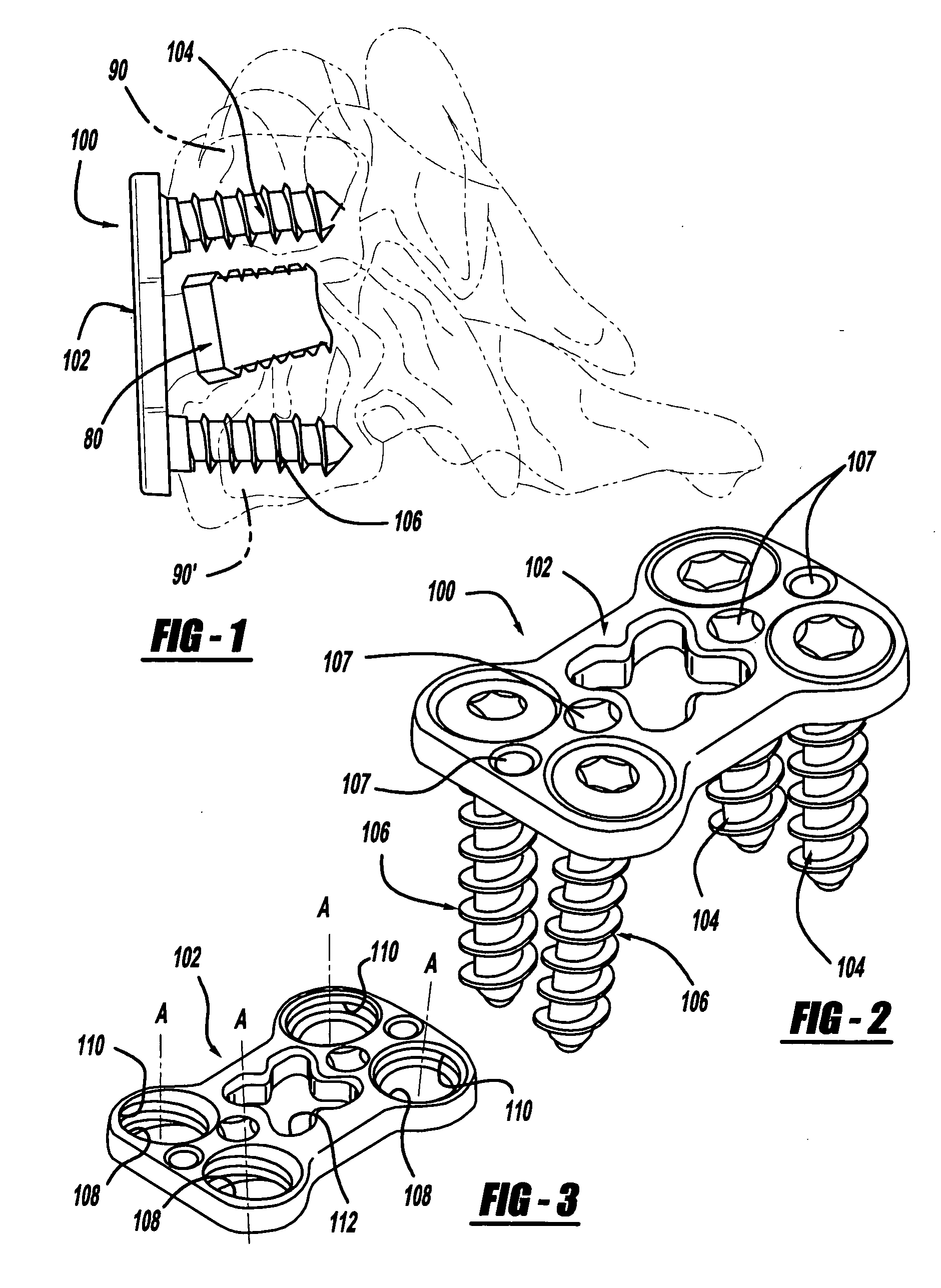
[0023] Referring to FIG. 1, an exemplary bone fixation system 100 according to the present teachings is illustrated as implanted in the anterior cervical spine for securing two cervical vertebrae 90, 90′ relative to one another, without interfering with any bone graft 80, which may also be implanted therebetween.

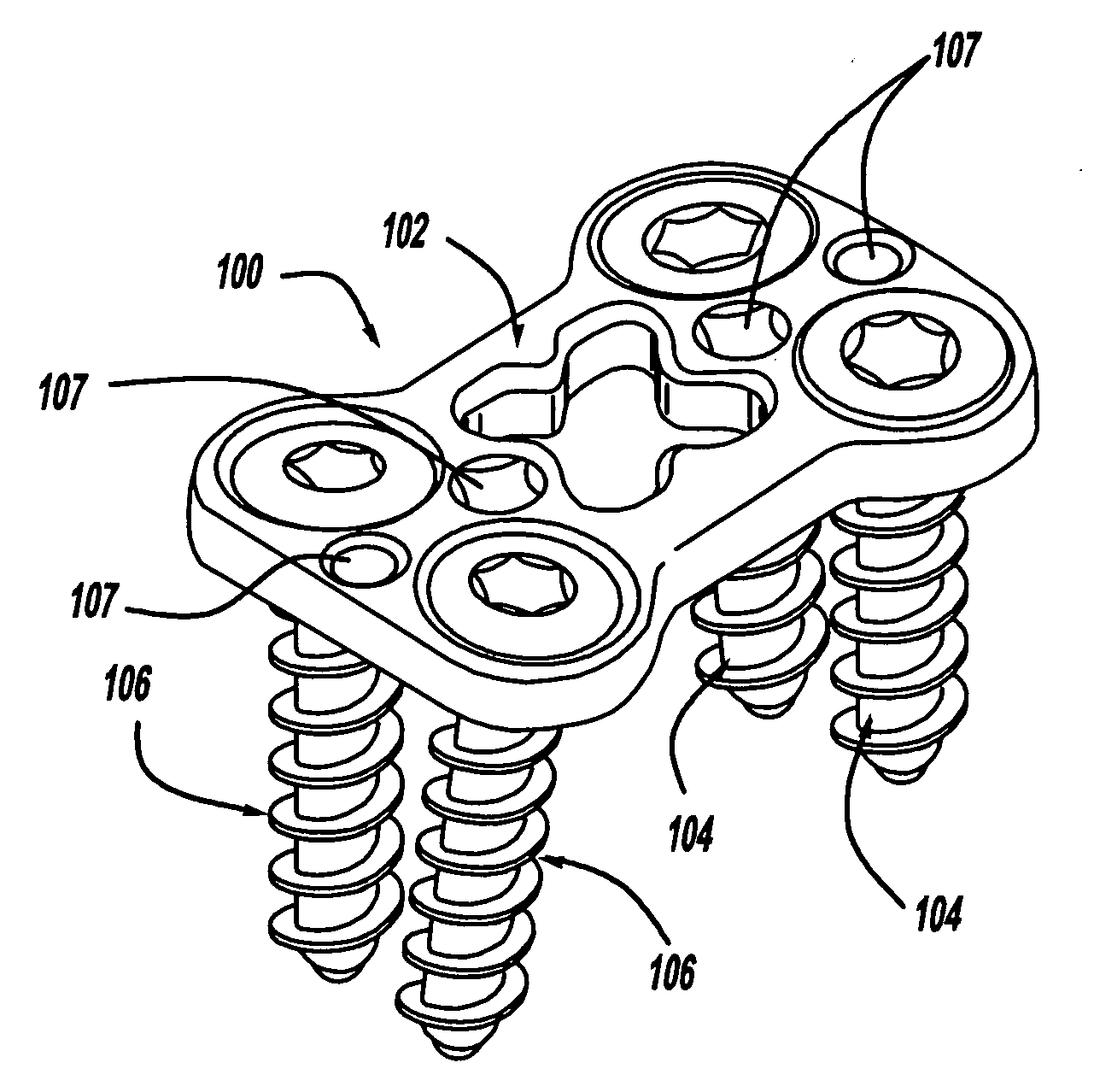
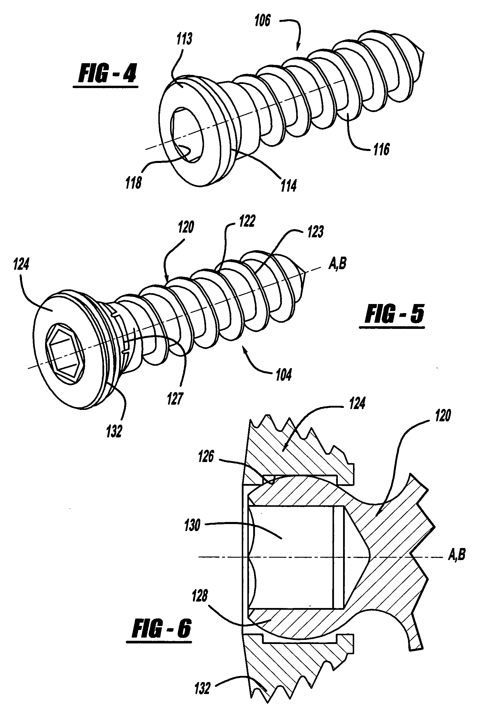
[0024] Referring to FIGS. 2-5, the bone fixation system 100 can include a fixation plate 102, and a plurality of fixation fasteners, including angulatable (semi-constrained) fixation fasteners 104 and non-angulatable (constrained) fixation fasteners 106. As used herein, the term “constrai...


PUM


Abstract

A bone fixation system. The bone fixation system includes a fixation plate including at least one fixation hole, and at least one fastener, the fastener including a coupler and a shank for engaging a bone. The coupler is threadably engaged with the fixation hole. The shank is angulatably retained by the coupler and orientable relative to the fixation plate at a selectable angle.

Description

INTRODUCTION [0001] In certain orthopedic surgical procedures, it is necessary to secure multiple bones or bone portions relative to each other. For example, in certain spinal surgeries, the fusion of two or more vertebral bodies is required to secure a portion of the spinal column in a desired position. This need may be the result of physical trauma from fractures or dislocations, degenerative diseases, or tumors. [0002] One such spinal fixation procedure involves the attachment of a prosthesis or plate to the anterior side of the cervical portion of the spine. The procedure requires anteriorly accessing the spine and securing a prosthetic plate to two or more cervical vertebrae. This allows fusion of the two or more cervical vertebrae in a particular orientation so to facilitate healing or to alleviate a condition of the patient. [0003] Various fusion plates and plating systems are known for anteriorly fusing the cervical spine. Such plates and plating systems must meet several re...

Claims


Application Information

Patent Timeline
IPC IPC(8): A61F2/30
CPCA61B17/7059A61B17/8047
Inventor ZIOLO, TARALEUNG, TAKKWONG ROSS
Owner ZIMMER BIOMET SPINE INC
Why Eureka
Try Eureka