Bone fixation device

a bone fixation device and bone technology, applied in the field of orthopedic surgical procedures, can solve the problems of large plate volume, adversely affecting intra-operative and postoperative viewing of the associate area of the spine, and conflicting requirements of spinal stability and system reliability over an extended period of us

Inactive Publication Date: 2005-10-13
ZIMMER BIOMET SPINE INC
View PDF99 Cites 113 Cited by
  • Summary
  • Abstract
  • Description
  • Claims
  • Application Information

AI Technical Summary

Benefits of technology

[0006] The present teaching provide a bone fixation apparatus that includes a bone fixation plate having a fixation hole, and a modular bone fixation fastener received in the fixation hole. The bone fixation fastener includes a shaft member and an expandable head member. The shaft member has an outer cam that mates with a corresponding inner cam of the head member, such that upon rotation of the head member relative to the shaft member, the head member radially expands to prevent back out of the shaft member relative to the bone fixation plate.

Problems solved by technology

Such plates and plating systems must meet several requirements that often are in conflict.
For example, the requirements associated with spinal stability and system reliability over an extended period of use often conflict with the requirements of an easy to use implant.
Strength requirements for a fusion plate tend to make the plate bulky and adversely effect intra-operative and postoperative viewing of the associate area of the spine.
Plating systems are also required to ensure that bone screws do not loosen over time or back out from the plate, further complicating the design of anterior plating systems.

Method used


Image

  • Bone fixation device
  • Bone fixation device
  • Bone fixation device

Examples


Embodiment Construction

[0035] The following description of various embodiments is merely exemplary in nature and is in no way intended to limit the invention, its application, or uses.

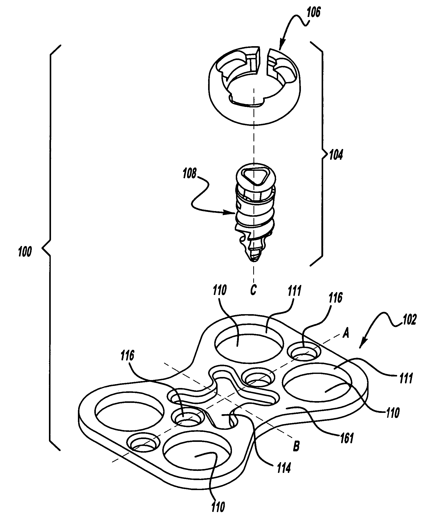
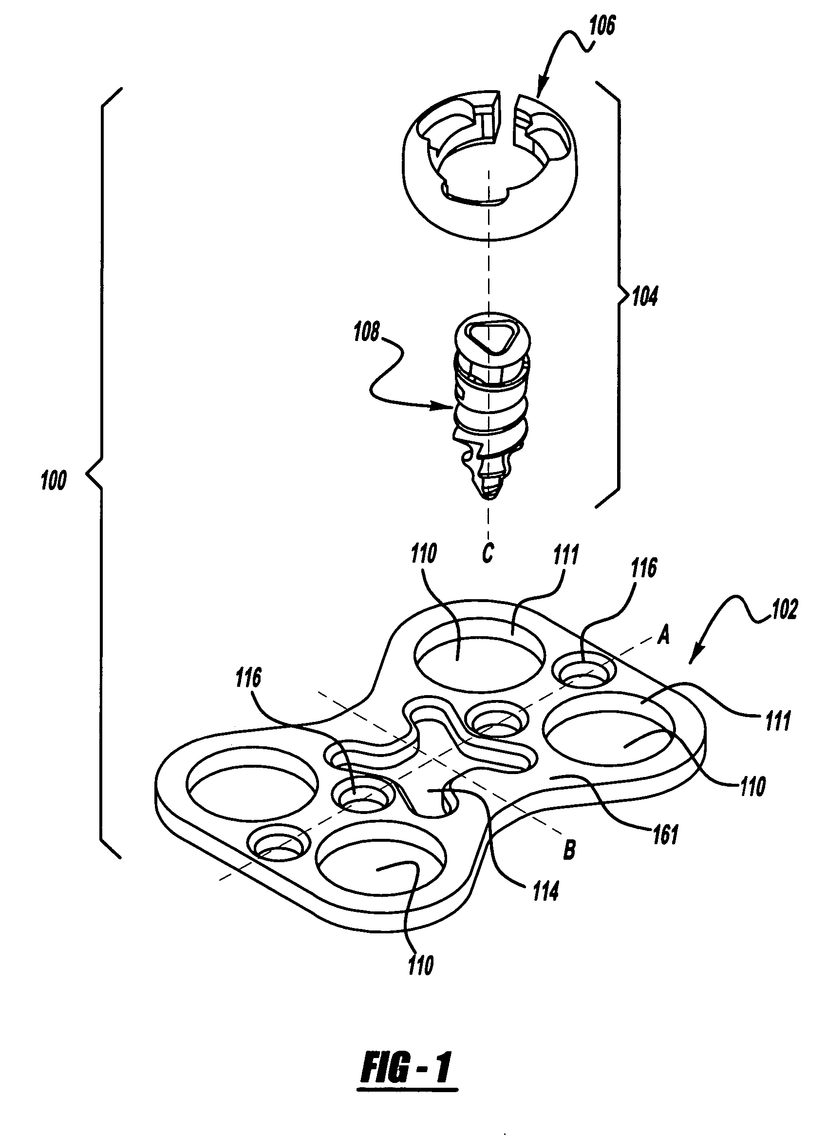
[0036]FIG. 1 illustrates an exploded view of a bone fixation apparatus 100 according to the present teachings. The bone fixation apparatus 100 generally includes a bone fixation plate 102 and a modular bone fixation fastener 104. The bone fixation fastener 104 includes an expandable head member 106 and a shaft member 108 having a shaft axis “C”. The bone fixation plate 102 includes one or more fixation holes 110 through which the bone fixation fastener 104 is inserted to be affixed to a bone portion.

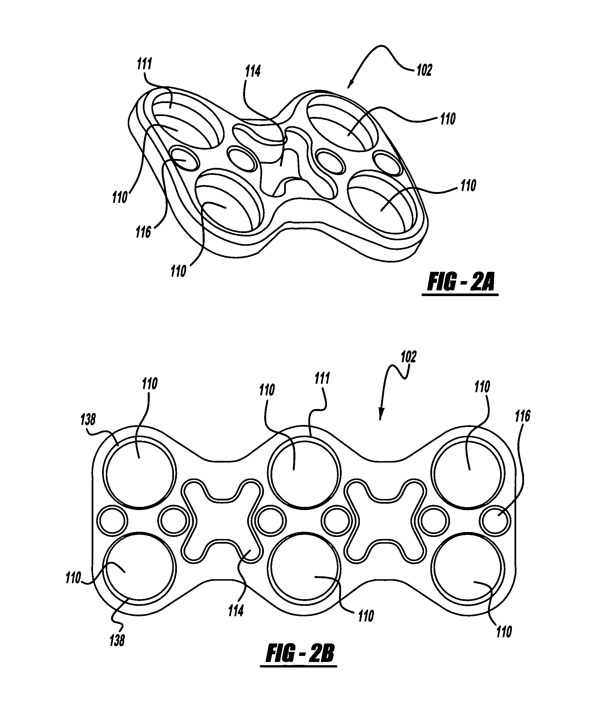
[0037]FIGS. 2a to 2d illustrate examples of fixation plates 102 adapted for fixing together two to five bone portions 90, respectively, such as, for example, the vertebral bodies shown in FIG. 16. In the exemplary fixation plates 102 of FIGS. 2a-2d, the fixation holes 110 are arranged in pairs, two for each bone portion 90. Oth...


PUM


Abstract

A bone fixation apparatus and associate method. The bone fixation apparatus includes a plate having a fixation hole, and a modular fastener received in the fixation hole. The bone fixation fastener includes a shaft member and an expandable head member. The shaft member has a outer cam at a first end mating with a corresponding inner cam of the head member, such that upon rotation of the head member relative to the shaft member, the head member expands against an inner surface of the fixation hole to prevent back out of the shaft member relative to the bone fixation plate.

Description

INTRODUCTION [0001] In certain orthopedic surgical procedures, it is necessary to secure multiple bones or bone portions relative to each other. For example, in spinal surgeries, the fusion of two or more vertebrae bodies is required to secure a portion of the spinal column in a desired position. This need may be the result of physical trauma from fractures or dislocations, degenerative diseases, or tumors. [0002] One such spinal fixation procedure involves the attachment of a prosthesis or plate to the anterior side of the cervical portion of the spine. The procedure requires anteriorly accessing the spine and securing a prosthetic plate to the one or more cervical vertebrae. This allows fusion of the one or more cervical vertebrae in a particular orientation so to facilitate healing or to repair a condition of the patient. [0003] Various fusion plates and plating systems are known for anteriorly fusing the cervical spine. Such plates and plating systems must meet several requireme...

Claims


Application Information

Patent Timeline
Patent Type & Authority Applications(United States)
IPC IPC(8): A61B17/58A61B17/80A61B17/86A61B17/88
CPCA61B17/8047A61B17/861A61B17/888A61B17/8685A61B17/8615
Inventor ZIOLO, TARAFERREIRA, RUI
Owner ZIMMER BIOMET SPINE INC
Why Eureka
Try Eureka